TOP-END REBUILD
2016 HONDA CRF250RThese instructions cover most modern top-end rebuilds. There are subtile differences between brands and specific models. Follow the links for the specific details. Always refer to the Service Manual for the final word. Most, but not all, top-end rebuilds can be done without removing the engine from the frame. This bike allows this. |

| Tools Required
- Torque wrench that accurately measures 0 to 75 ft-lbs SnapOn Digital Torque Wrench shown) - Hi-Strength Loctite - Feeler Gauges - Metric calipers and micrometer - Assembly Lube |
PRELIMINARY Wash and dry the bike completely. Remove the Seat, Gas Tank, Airbox, Exhaust. Drain the Coolant and Oil(s). Dispose of the oil properly. Most of the time the Coolant can be reused. If it is dirty dispose of it properly. |
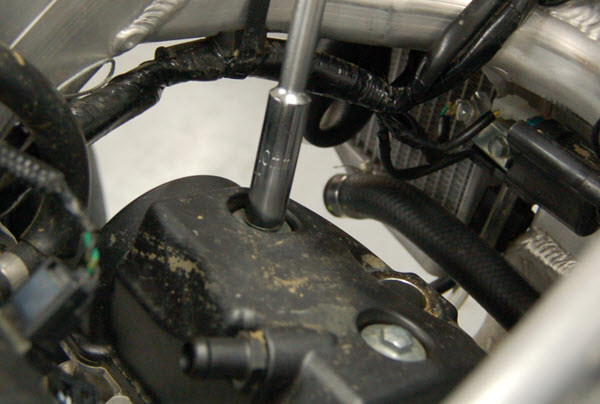
| D1- Remove the Valve Cover. |
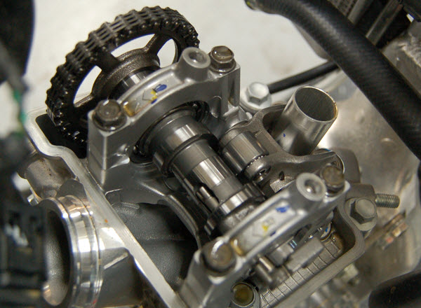
| D2- Before going any further your engine needs to be at TDC (Top Dead Center) of the compression stroke so that nothing binds or damages it self during disassembly. |
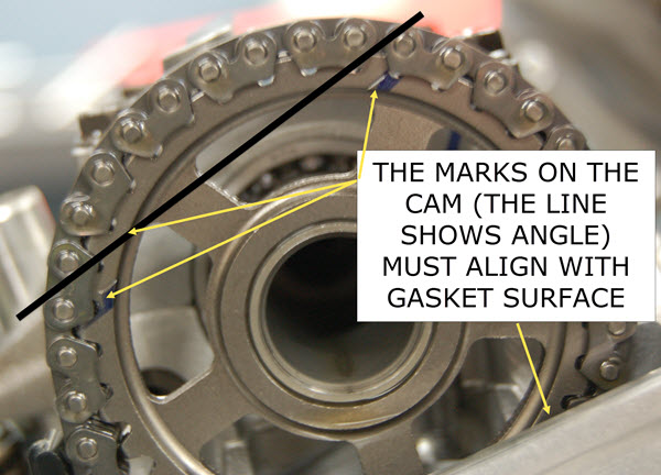 | D3- As you can see this Engine is not at TDC so we will fix that now. |
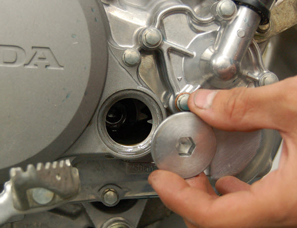 | D4- Remove the Inspection Plug. |
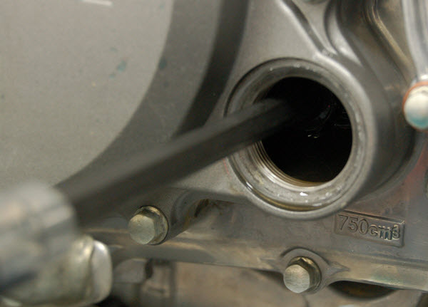 | D5- Using a Long 8MM Allen, Turn the Primary Gear Clockwise. (This is the Natural Rotation of the Engine). |
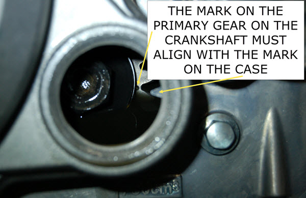
| |

| D6- The Cam Lobes should be positioned something like this. |
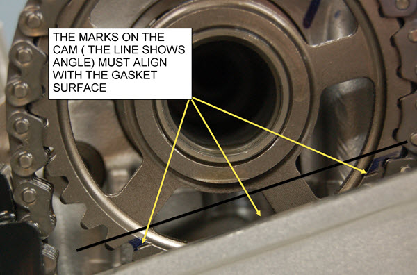 | D7- To be positive youll need to look at the timing marks located on the cam sprocket. |
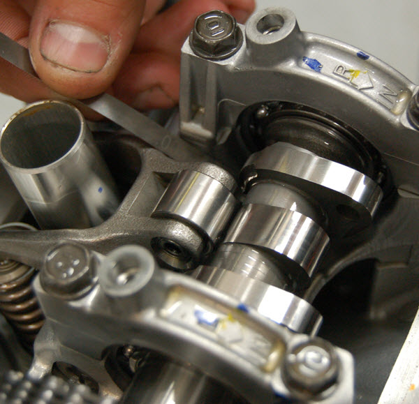 | D8- Once everything is in the right position we like to check Valve Lash before we continue with Disassembly. |
 | D9- If you choose to do this, Take note on what the valve lash is so you dont forget. (Refer to your Owners Manual for the Factory Tolerance). |
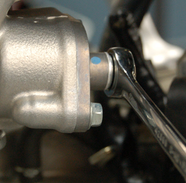 | D10- Loosen the retracting cover bolt before you remove the tensioner to make retracting the plunger an easier process during assembly. |
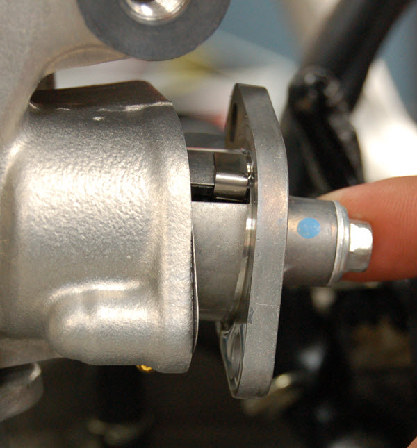 | D11- Remove the Tensioner. |
 | D12- Remove the bolts from the cam caps. |
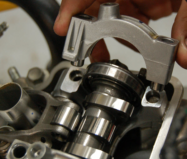 | D13- Gently remove the caps. (You shouldnt have to force these off). |

| D14- Be sure to remove the Cam Thrust Washers. (You dont want to drop these in the engine). |
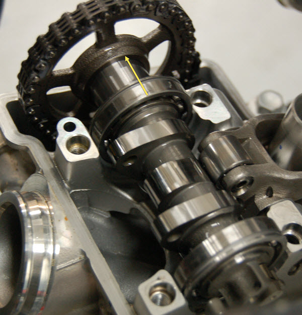
| D15- Slide the Bearing towards the Cam Sprocket to allow the cam to pivot downward. |
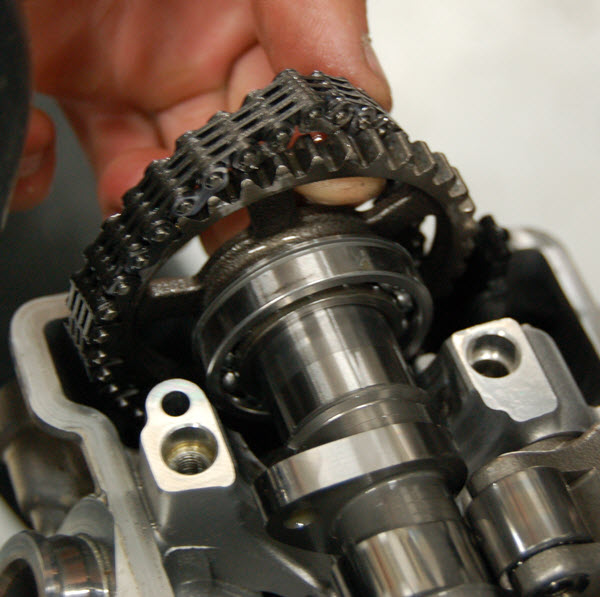
| D16- This will allow you to remove the cam chain from the sprocket and get the Camshaft out. |
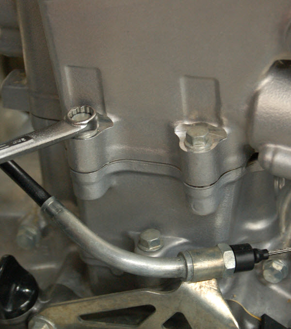
| D17- Remove the cylinder head flange bolts. |
 | D18- Loosen, but do not remove the cylinder flange bolt. (This will allow the cylinder to stay down when you pull the cylinder head off without having to hold the cylinder). |
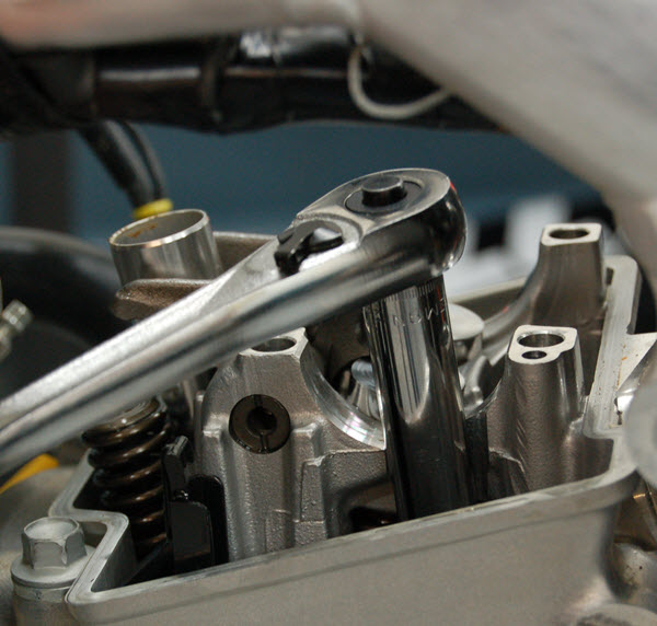
| D19- Use a large ratchet or something with good leverage to unscrew and remove the engine bolts. |
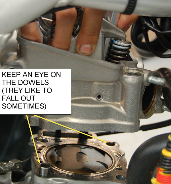 | D20- Remove the cylinder head gently, the more you fight with it and force it, the harder it will be. Note- If it does not want to come off, double check to make sure you've removed all the bolts |
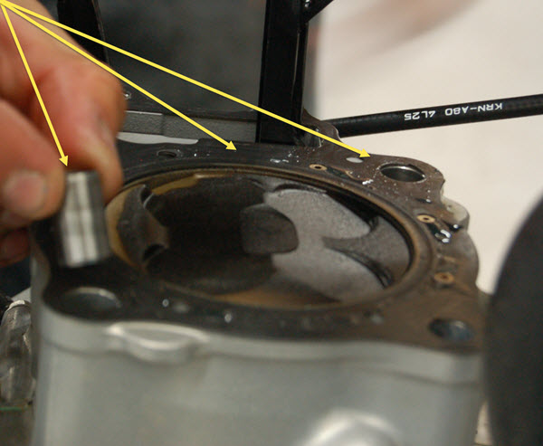 | D21- Remove the Dowels and Head Gasket. The Dowels will stay in the cylinder head sometimes. Double check and make sure you have both of them so one doesnt fall out and get misplaced). |
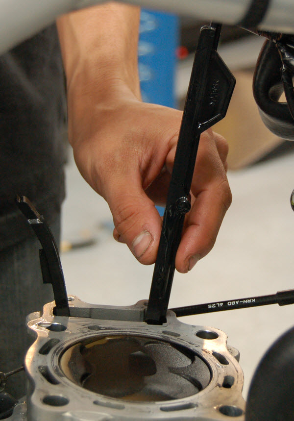 | D22- The Cam Chain guide will slide up. |
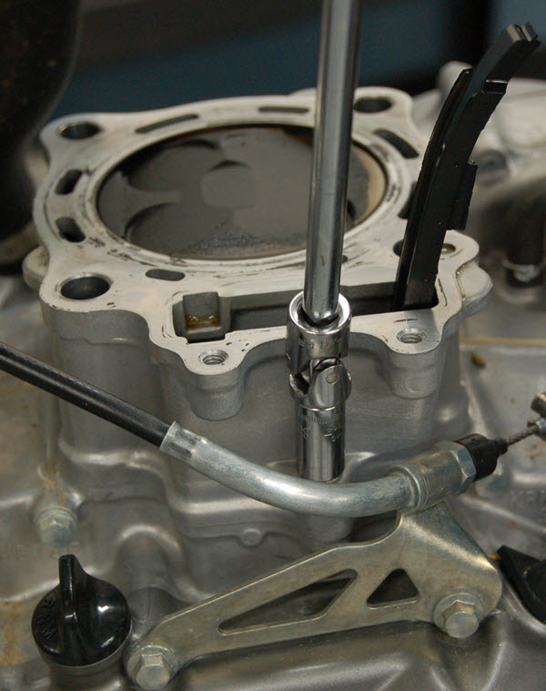 | D23- Remove the cylinder flange pinch bolt. |
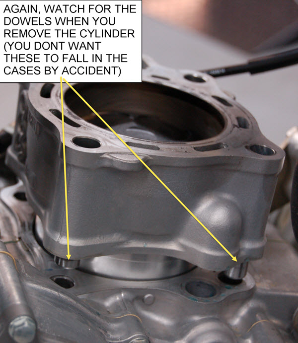 | D24- Pull the cylinder upward. |
 | D25- Remove the Two Dowels, Along with Gasket. |
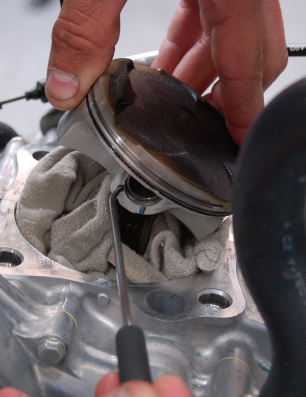 | D26- Stuff a rag into the crank case so nothing can fall in. Using a pick, remove the piston clip (Usually best to remove what ever side doesnt have as much clutter blocking it). |
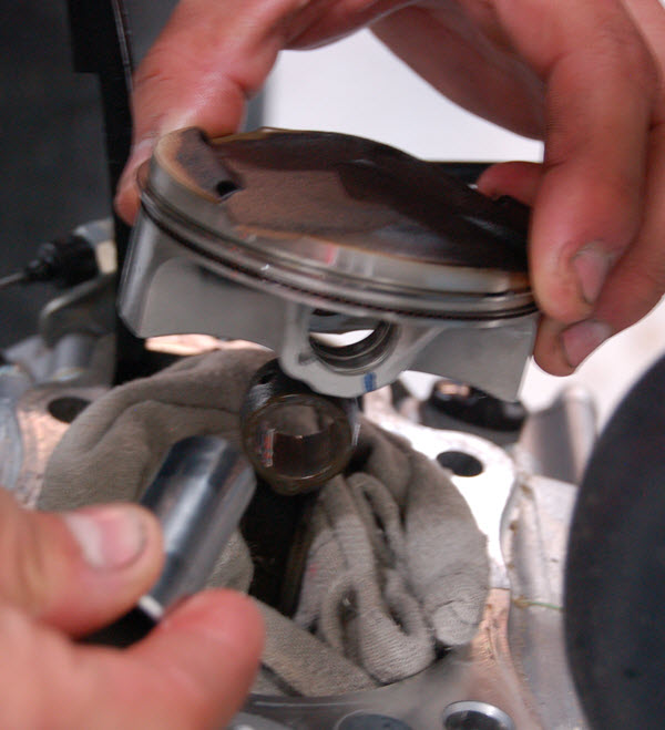
| D27- Slide the Piston Pin out (Check for unusual wear). |

| CD1- Slide the rocker arm shaft to either side. |
 | CD2- Set rocker arm to the side. |
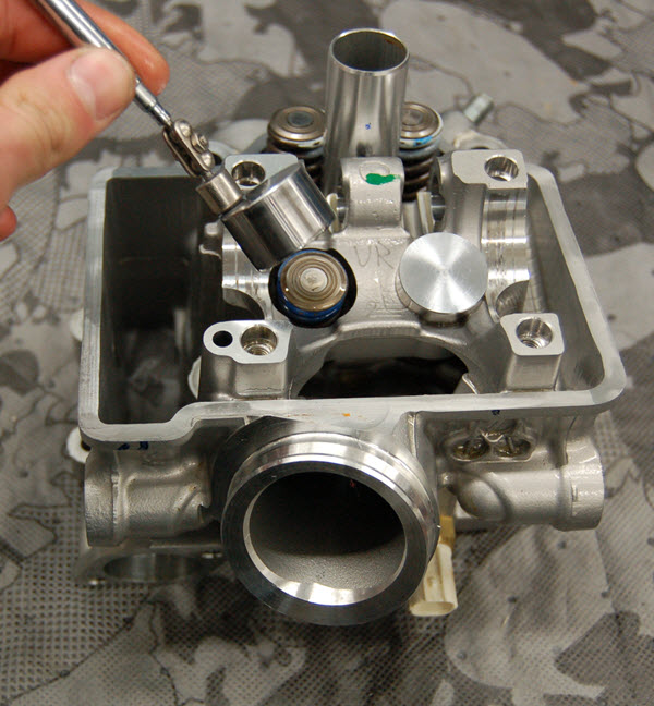 | CD3- Using a Magnet, you can easily remove the Camshaft Buckets. |
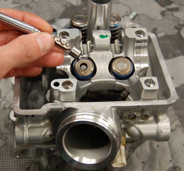 | CD4- Remove the shims as well. |
 | CD5- Using a valve spring compresssor, Compress the valve spring and remove the keepers using a magnet (If you're using Titanium keppers youll need to use Tweezers). |

| CD6- Remove the valve springs. If you're uncertain and think youll mix the springs up, set them aside in the order you remove them. Always refer back to your Owners Manual. |
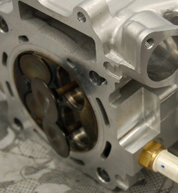
| CD7- Remove the Intake Valves. We like to keep them in the order we took them out. |
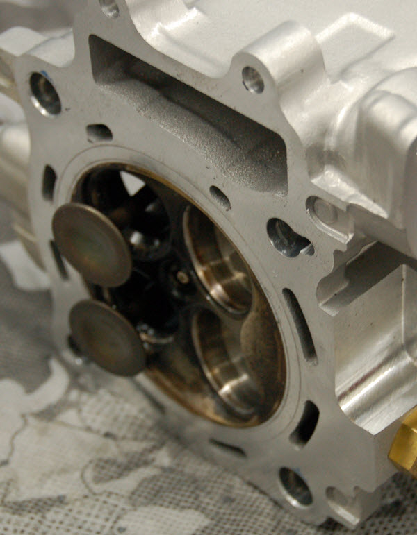
| CD8- Do the same for the Exhaust Valves. |
 | CD9- Inspect the valve seats for any wear or damage. at this point you can send your cylinder head to us for further inpection and a valve job. |
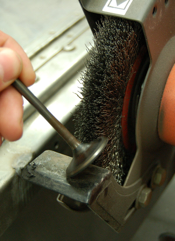
| CD10- Clean the carbon off the valves with a Non-Aggresive wire wheel |
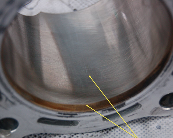 | CI1- Look for wear on the cylinder. it is a must to have your cylinder honed if you are replacing your Piston or Rings. |

| PI1- The arrows show where the the most wear will be on the piston. |
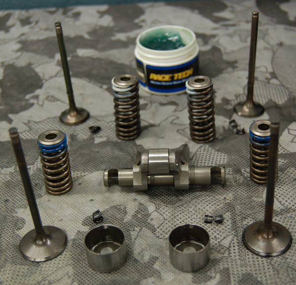 | CA1- Once everything has been Thouroughly Cleaned and Inspected, You are ready for assembly. |
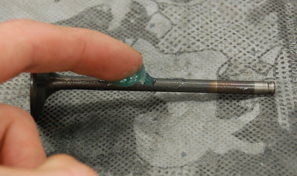
| CA2- Lube the stem of each valve with a thin layer of grease or assembly lube. |
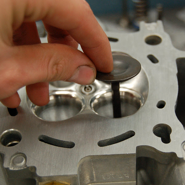 | |
 | CA4- Repeat steps CA2-CA3 for each Additional Valve. |
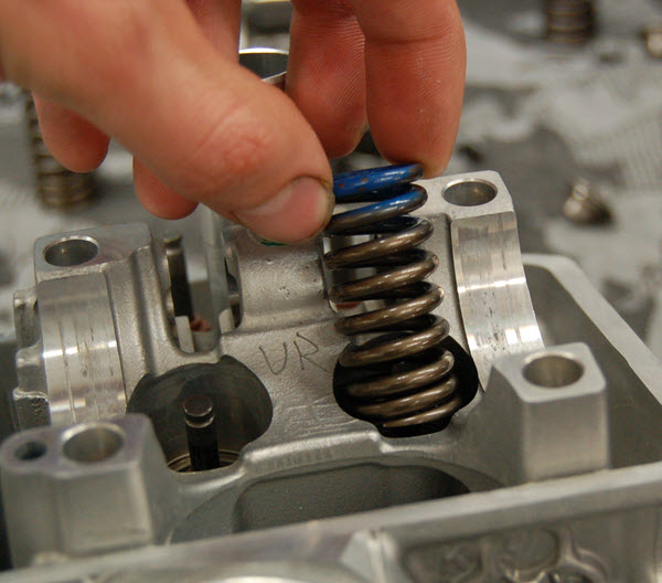 | CA5- Place Intake Springs around the valve. (Be sure there is a spring seat that the spring sits on). |
 | CA5- Do the same for the exhaust springs. |
 | CA6- Insert the keepers into the spring retainer. |
 | CA7- The keepers will hold themselves in the retainer. |
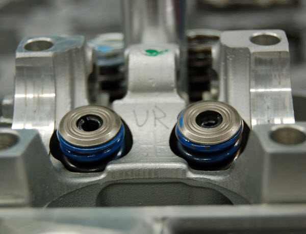 | CA8- Put your spring retainers on each valve spring. |
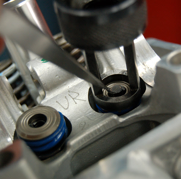
| CA9- Using a Valve Spring Compresssor, Carefully install the keepers into the groove on the tip of the valve. |
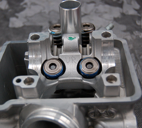
| CA10- Repeat the previous step for the rest of the Valves. |
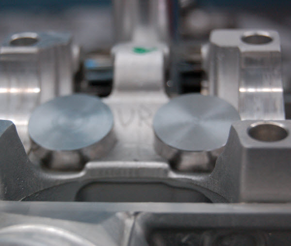
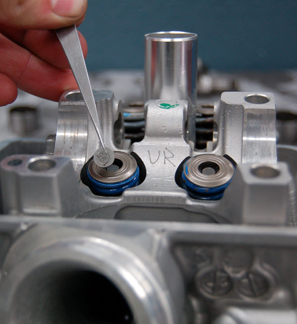 | CA11- Insert the existing shims. |
| |
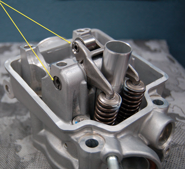 | CA13- Install the Rocker Arm and Rocker Arm Shaft. |
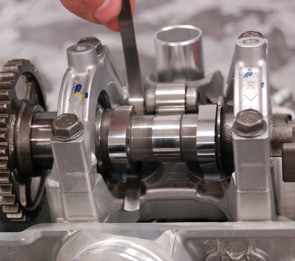 | CA14- Install the Camshaft and Cam Caps to check valve lash. (Refer to your owners manual for the specified tolerance). |
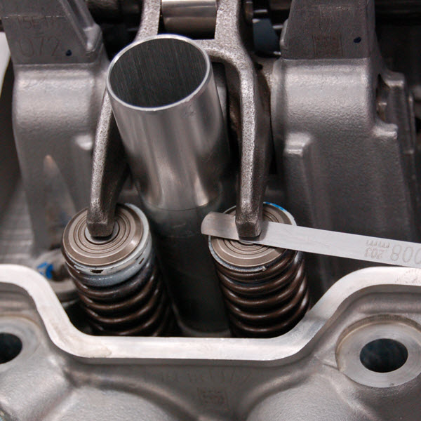 | CA15- Do the same for the exhaust side. |

| CA16- Once your valve lash is set to the desired tolerance, You'll want to remove the shims and put a dab of grease or assembly lube in the shim location. |
 | CA17- The Grease will help retain the shims. |
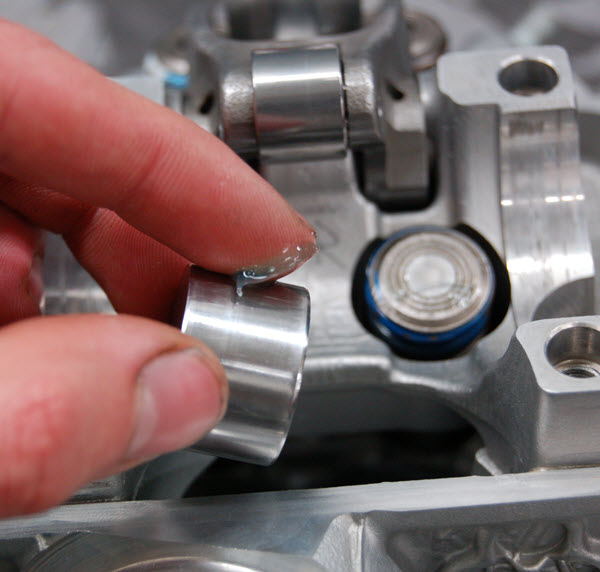
| CA18- Apply a thin layer of grease or assembly lube to the Bucket Skirt. |
 | CA19- Put a dab of grease or asembly lube on the top of the buckets and roller bearing. ( These will be the last components to get oil when you first start your engine so you want them lubed well). |
 | A1- You're ready for assembly. |
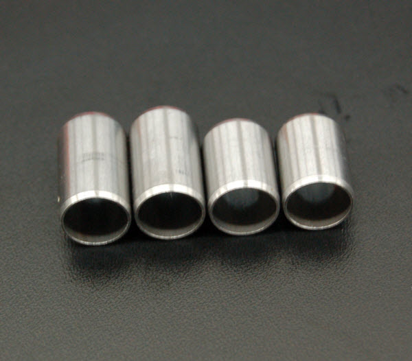 | A2- Remember that the cylinder and cylinder head dowels are different lengths. |
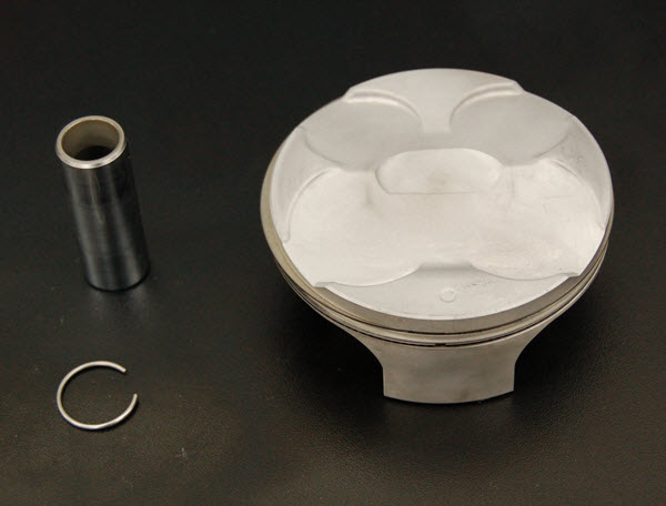 | A3- Have your Piston, Pin, and Clip ready. |
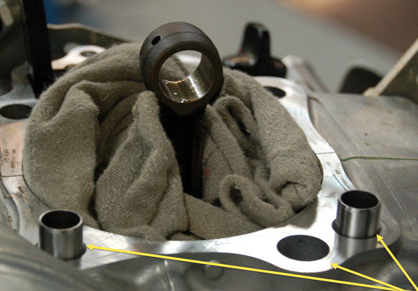 | A4- Install the short dowels and Cylinder Gasket. |
 | A5- Line the piston up with the rod and slide the pin through. |
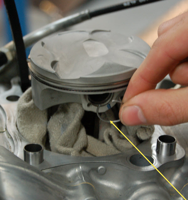 | A6- Insert the retaining clip. (Always use new clips). |
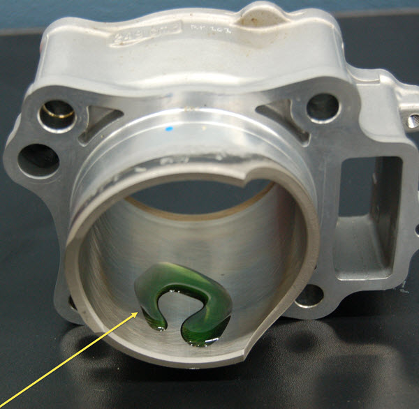 | A7- Apply a thin coat of engine oil around the cylinder walls. |
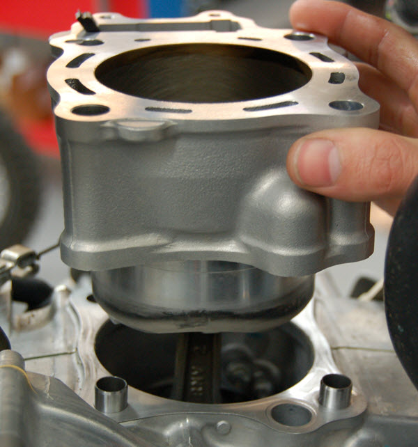 | A8- Compress the Compression and Oil Rings to slide the Cylinder over the Piston. |
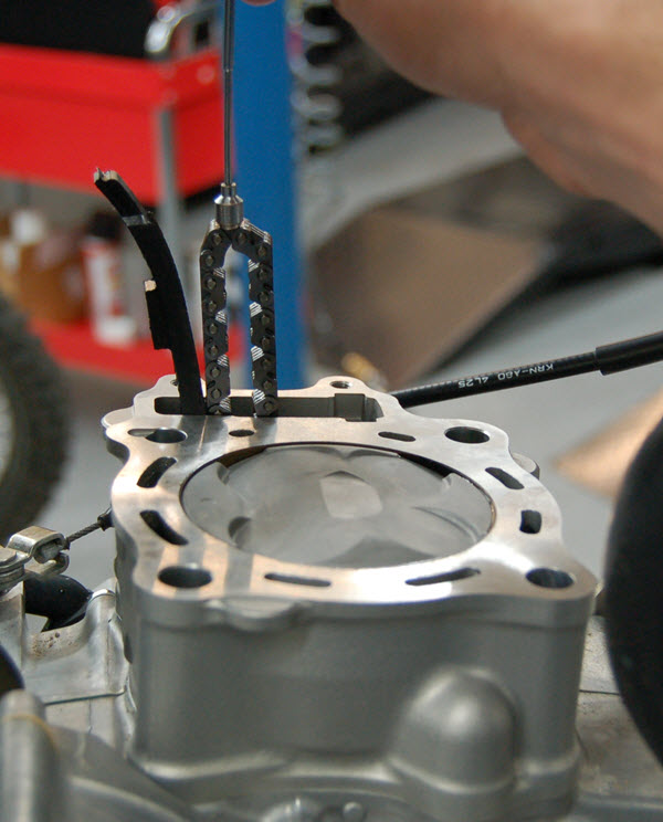 | A9- Pull the Cam Chain out using a magnet. |
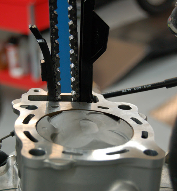 | A10- While you have the Cam Chain, install the Cam Chain guide.( Be sure the guide is in its correct location). |
 | A11- Install the Cylinder Head Dowels and Head Gasket. |
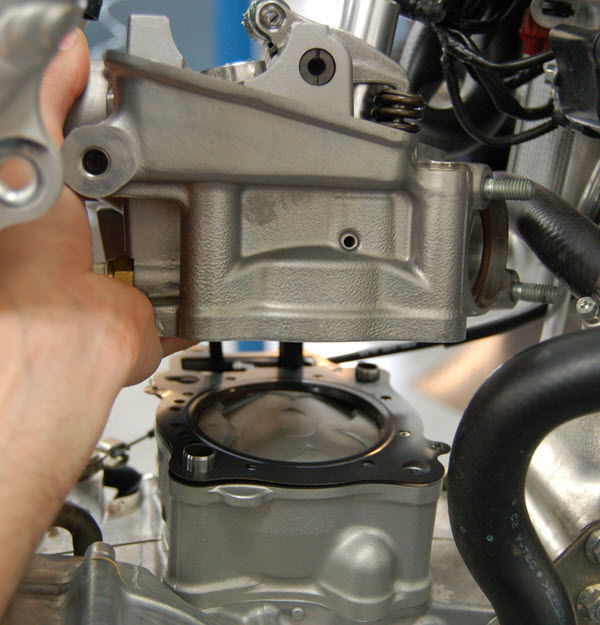
| A12- Gently place the cylinder head on the cylinder. Watch the camchain guide to make sure it doesnt come out of its location. |
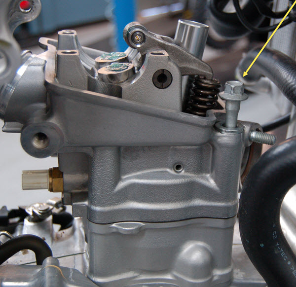
| A13- Snug all the engine bolts. |
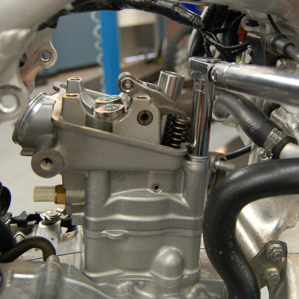
| A14- Apply torque evenly across the cylinder head. (Refer to your owners manual for torque specifications). |
 | A15- Tighten Cylinder and Cylinder Head Flange Bolts. |
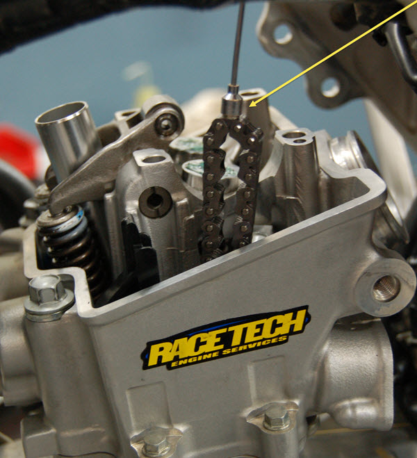
| A16- Using A magnet, Bring the cam chain up to set cam timing. |
 | A17- Use previous steps from D15-D16 to set cam timing. (Remember that the piston needs to be at TDC when you're doing this process). |

| A18- Install the Cam Thrust Washers. |
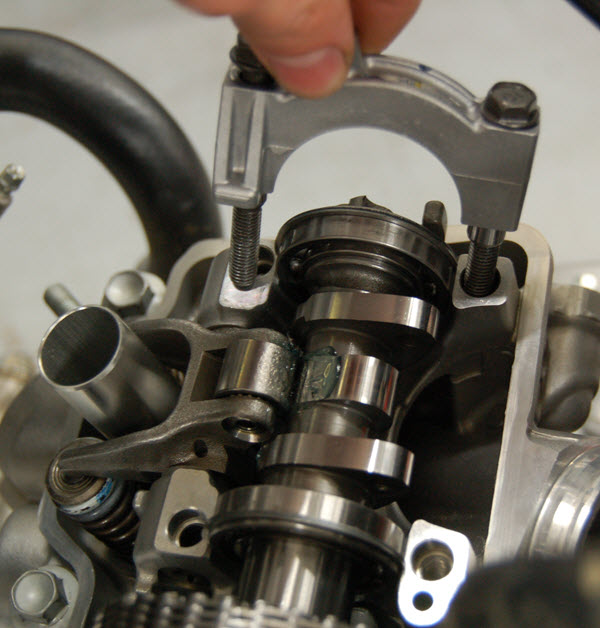 | A19- Install the cam caps and snug the bolts. |
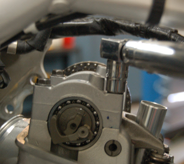
| A20- Torque cam cap bolts evenly( Refer to your owners manual for specified torque). |
 | A21- Using a small flat tip screw driver or cam chain retracting tool, turn clockwise to retract the plunger. |
 | A22- It will lock in place |

| A23- While the plunger is still retracted, intall the Cam Chain Tensioner. |
 | A24- Release the plunger by slightly turning the tool counter clock wise while pulling the tool out so the retractor will unspool automatically. |
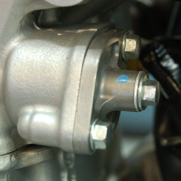 | A25- Install the retraction cover bolt and torque to spec. |
 | A26- Turn the engine over manually to ensure everything moves freely and no components will hit upon start up |
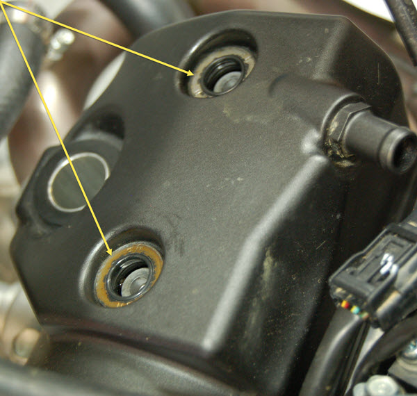
| A27- Place the Valve Cover on the cylinder head along with the Bolt Washers. These washers are marked with the correct side that faces up. |
 | A28- Install and Tighten Valve Cover Bolts |
| |