Fork Gold Valve InstallationVALVING AND ASSEMBLY INSTRUCTIONS
|
|||||||
|
|
Tools
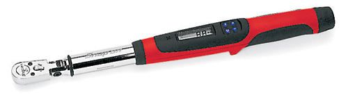
- Torque wrench (SnapOn Digital Torque Wrench shown) - Metric calipers and micrometer
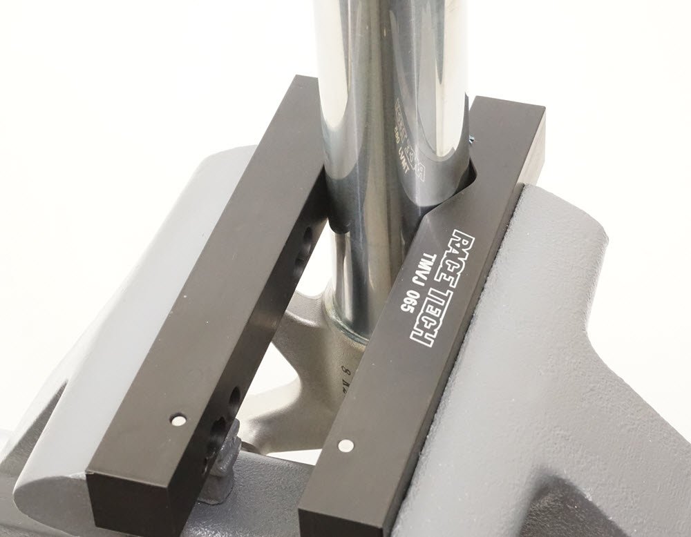
- TMVJ 065 Vise Jaws mounted on a Vise - suggested - TSCP 01 - Clip Tool
- TFCA TF08 - Two Flat 8mm SocketXXXXXX Supplies
Contact Cleaner - or other good, clean solvent
Loctite - Hi-Strength (included in the Gold Valve Kit)
USSG 01 - Ultra Slick Seal Grease
USF-05 - Fork OilXXXXXX |
||||||
|
|
|||||||
|
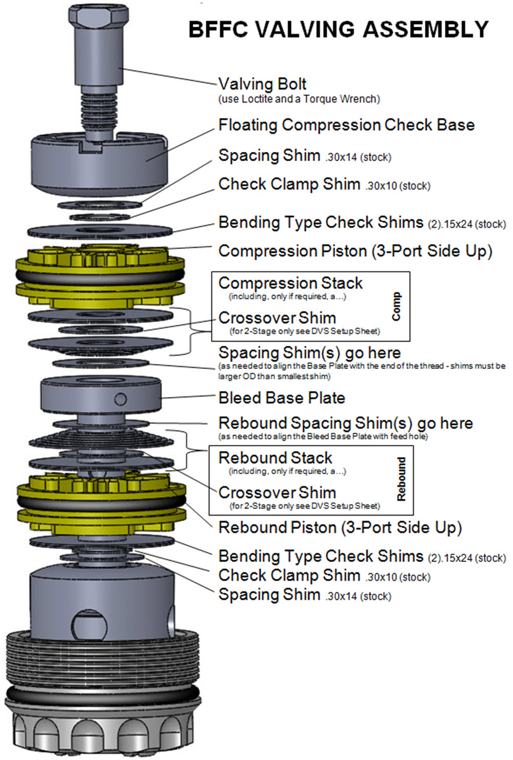
You will either be building a Single Stage or a Two Stage Stack (or possibly a combination of both). The difference is the Crossover. The Crossover is a smaller diameter shim between the Lo-Speed and the Hi-Speed Stacks. Look for this shim in the valving stack listed in the DVS. If it is not there it is a single stage stack. Note: The DVS Custom Setup Sheet displays individual shims and does not label Hi-Speed, Crossover, and Lo-Speed. This is for your information only. Also you will not use all the shims provided in the Gold Valve Kit.
|
|||||||
|
|
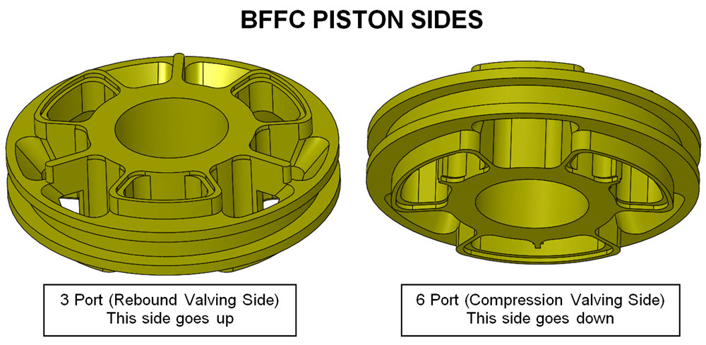
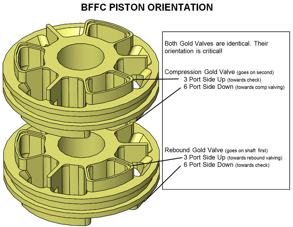
V2- IDENTIFY THE 3 AND 6 PORT SIDES OF THE PISTONS
The 3 port side is on the left - this side faces up
The 6 port side is on the right - this side faces down
|
||||||
|
|
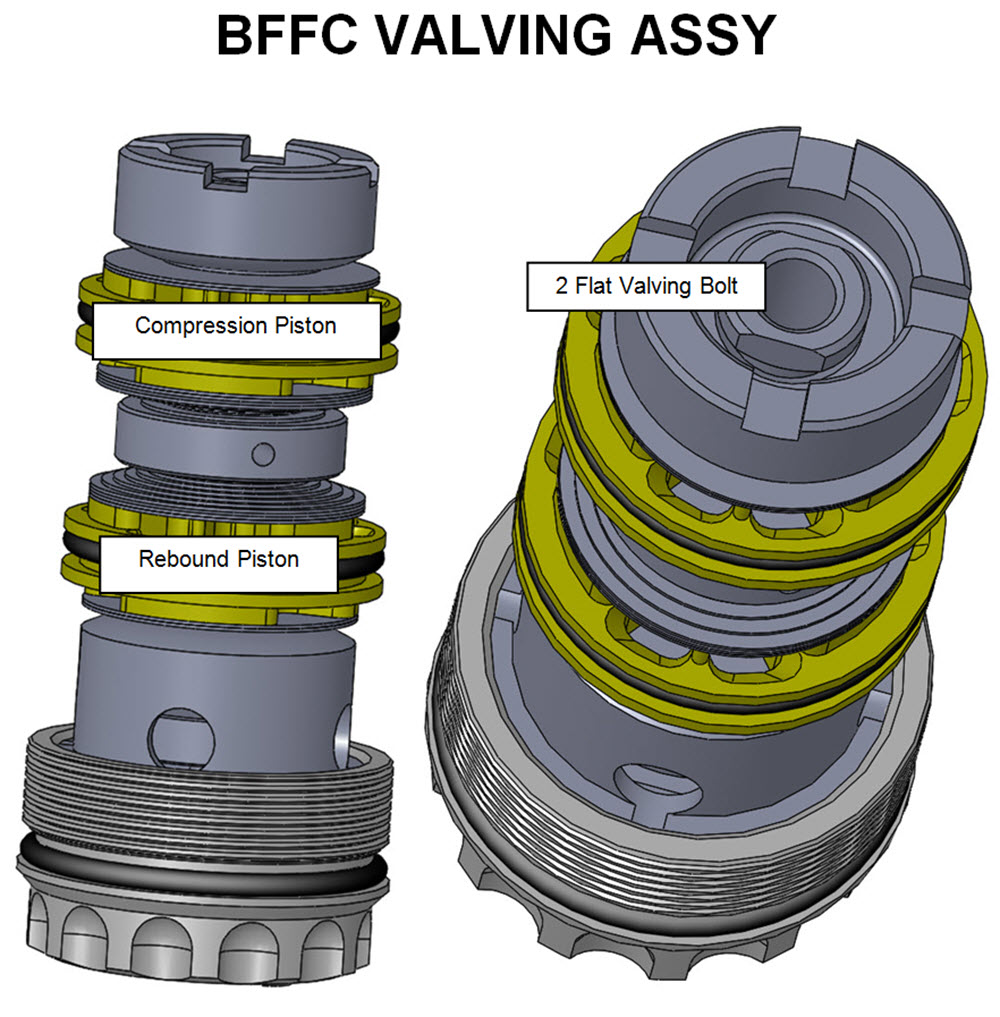
V3- Rebound Assembly (bottom valve - installed on shaft first)
Assembly order: Stock Check Valve Assembly Spacing Shim (.30x14) Rebound Gold Valve - 3 Port Side up, 6 Port Side down (rebound and compression Gold Valves are identical and the 3 port side faces up on both - critical)
|
||||||
|
|
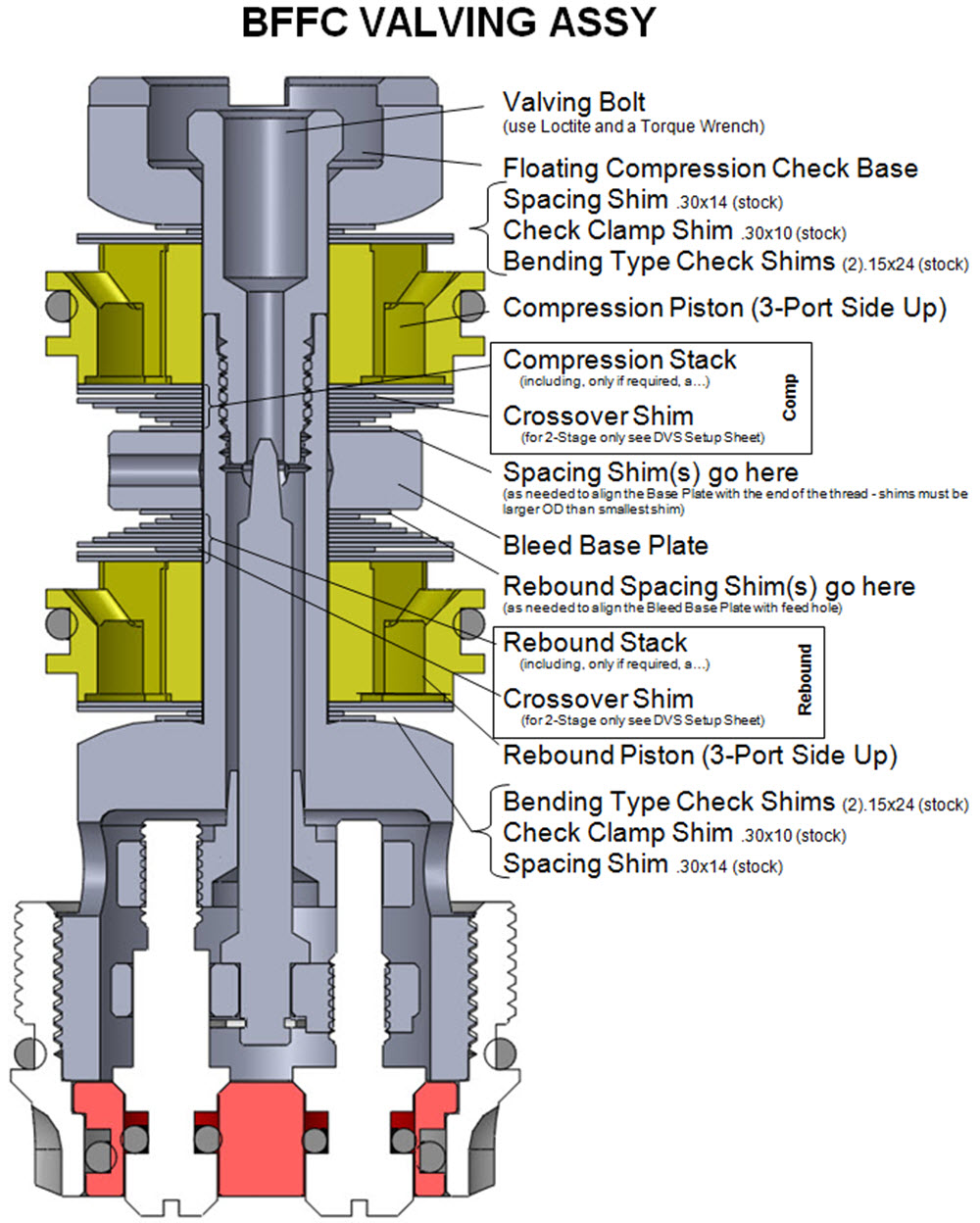
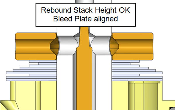
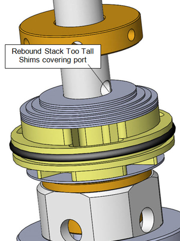
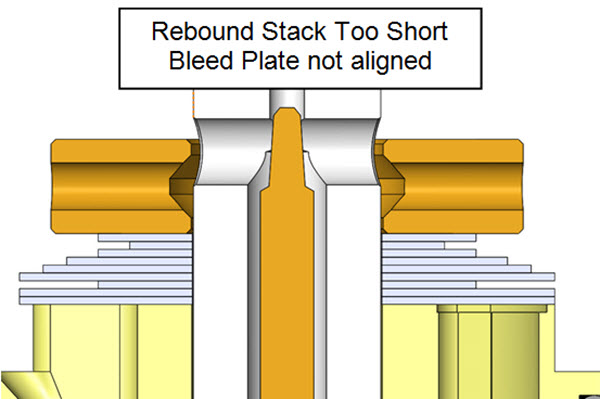
V4- Make sure the Rebound Valving Stack Height is correct. Critical!!
This step is here to insure the Bleed Base Plate is aligned with the feed holes in the shaft.
This should be ok with the valving selected by the DVS. If it is not, double check everything.
If needed, height adjustment is done with Spacing Shims added just below the Bleed Base Plate.
Spacing Shims must be larger in diameter than the smallest shim in the stack.
|
||||||
|
|
V5- Compression Assembly(top valve - installed on shaft second)
Note: If Spacing Shims are required to achieve the correct Total Valving Stack Height they will be placed directly on top of the Bleed Base Plate. (see the next step)
Example: for Two Stage the total Compression valving stack is made up of a:
Hi-Speed Compression Stack
Compression Crossover and a
Lo-Speed Compression Stack
Note: The DVS Custom Setup Sheet displays individual shims and does not label Hi-Speed, Crossover, and Lo-Speed. (this is only an example - not your setting)
The Total Valving Stack starting from the Gold Valve piston face: (4) .15x24 - Lo- Speed Stack
(1) .10x12 - Crossover (notice the smaller diameter) (1) .20x24 - Hi- Speed Stack
(1) .20x22
(1) .20x20
(1) .20x18
(1) .20x16
(1) .20x14 (1) .20x12
(1) .20x10
Install the compression valving stack in the REVERSE order that it is listed on the DVS, starting with the smallest diameter shim of the Hi-Speed Compression Stack tapering up to the largest, then the Compression Crossover, then the Lo-Speed Compression Stack.
Install the Compression Gold Valve (3 Port side up, 6 Port side down).
Stock Check Valve Assembly Bending Type Check Shims (2).15x24 Clamp Shim (.30x10)
Spacing Shim (.30x14)
|
||||||
|
|
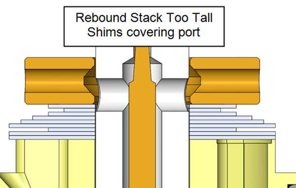
V6- Make sure the Total Valving Stack Height is correct. Critical!!
This is an unusual design in that the valving stack is not tightened down with the valving bolt. It is tightened when the Valving Assembly is installed into the fork bottom. Therefore the most important thing about setting the Total Stack Height is making sure the Compression Base Plate floats with the two-flat bolt tight. This should be ok with the valving selected by the DVS. If it is not, double check everything. If needed, height adjustment is done with Spacing Shims added just above the Bleed Base Plate below the Comression Valving Stack.
Spacing Shims must be larger in diameter than the smallest shim in the stack.
|
||||||
|
V7- Re-use the stock valving bolt.
Clean everything completely.
Install and torque the valving bolt to the proper setting (see the DVS) using a torque wrench. This is critical!
|
|||||||
| V8- Single Stage Compression and Rebound
Examples on conventional shocks (but you get the idea). |
V9- Two Stage Compression and Rebound
Notice the gap in the valving stack where the Crossover is. The Crossover Gap should be clearly visible. |
||||||
|
|
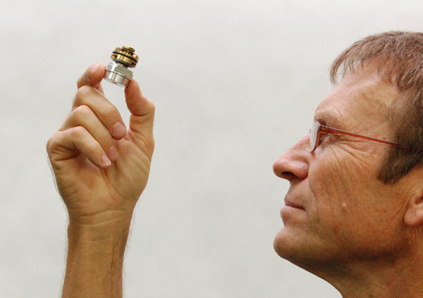
V10- Visually check your work.
Hold the completed valving assembly up to the light and look for any irregularities. Make sure the shims are laying flat on the piston surface. On two stage stacks check that the Crossover Gap is clearly visible.
If there are any problems, disassemble the stack and look for dirt, bent shims, or any other causes. Reassemble and inspect again.
You might be thinking that this looks like either a very tiny shock shaft or a fork compression valve. Well, you're right, it's a very tiny shock shaft. You get the idea.
|
||||||
|
|
V11- Make sure the shims that go next to the Gold Valve completely cover the ports on both sides of the piston! If the ports are not covered there will not be enough damping.
This could be caused by a number of reasons. Re-check everything.
Please call Tech Support if you can't figure it out.
|
||||||
| 1. ASSEMBLE FORK, INSTALL CARTRIDGE, INSTALL RESY, INSTALL VALVING ASSEMBLY 2. INSTALL SPRING AND SET OIL LEVEL – 230mm / 165cc??? 3. INSTALL PRELOAD TUBE AND FORK CAP, TIGHTEN LOCK NUT, TIGHTEN FORK CAP INTO TUBE 4. INSTALL RESY BLEED TOOL TFRS B2738 ON TOP OF RESY PISTON AND INSTALL CIRCLIP 5. INSTALL VACUUM BLEEDER ADAPTER AND HOOK UP VACUUM MACHINE 6. PERFORM VACUUM BLEED PROCEDURE 7. REMOVE RESY BLEED TOOL 8. SET RESY PISTON HEIGHT 60MM TO EDGE OF PISTON FROM TOP OF RESY TUBE 9. INSTALL RESY CAP AND CIRCLIP 10. LAY FORK HORIZONTAL AND REMOVE BLEEDER ADAPTER 11. LOCK TITE AND INSTALL BLEED BOLT 12. CHARGE RESERVOIR WITH 75psi NITROGEN 13. CLEAN FORK AND INSTALL RACE TECH STICKERS |
V12- Return to the main Rebuild instructions to complete the reassembly.
|
||||||
| • Single Stage - made of: Lo-Speed Stack Hi-Speed StackThere is NO Crossover (it becomes one stack.) |
 |
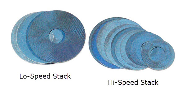 |
| • Two Stage - made of: Lo-Speed Stack Crossover Hi-Speed StackThe Crossover Gap is visible |
 |
 |