FORK COMPRESSION and REBOUND
|
|||||||
|
|
Tools Required
- In-lb torque wrench that accurately measures 0 to 50 in-lbs (0.58 kgf-m) (SnapOn Digital Torque Wrench shown)
- Hi-Strength Loctite (included)
- Metric calipers and micrometer
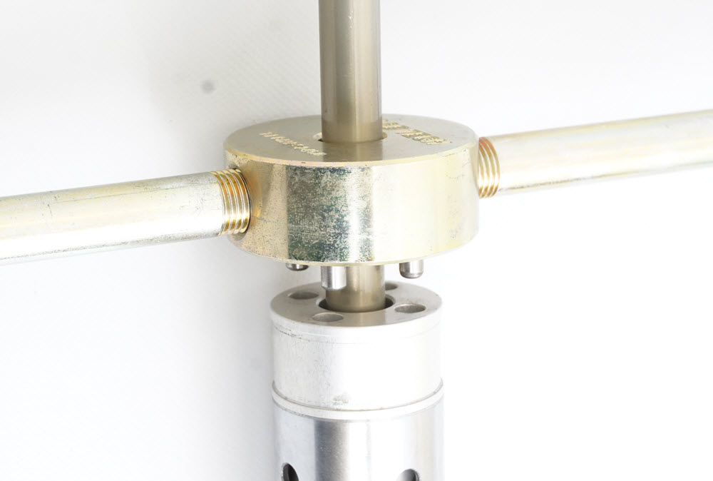
- TPSH 1225 Shaft Holding Tool (included),
- Propane Torch
- TMPS 02 Pin Spanner or TFCH PS24050 Seal Head Tool
|
||||||
|
|
DISASSEMBLY D1On the Damping (right) Leg remove the Fork Cap, Jam Nut and Bottom-out Spacer. Remove the Adjusting Rod from the center of the shaft. |
||||||
|
|
D3Gently pry off the Dust Seal. This will expose the Seal Clip. Remove the Seal Clip with a small screwdriver (the stock clip can be a pain as on some of them one end is tapered in and one tapered out, find the “easy-to-grab-with-a-small-screwdriver-or-clip-tool-end”). Slide hammer off the Outer Tube (this may bend the Seal Washer – don’t worry, see Assembly). |
||||||
|
D4Remove the Seal Head from the Inner Fork Tube. The Seal Head is Loctited into the top of the Fork Tube. Remove the Outer Bushing and use a propane torch to heat the top of the tube to help release the Loctite. Aim the flame towards the Seal Head between the holes. Use gloves (so you don’t burn your hand) and a TFCH PS24050 or a Pin Spanner to remove the Seal Head. Remove the Rod Assembly, pour out the Oil and dispose of it properly. Make sure you remove any stock plastic Preload Washers at the bottom of the Fork Tube. More than likely they will want to stick to the bottom just with the oil. If you look down the tube and it looks like a big Torx nut, a Preload Washer is still in there. |
|||||||
|
|
D5Slide off the Top-out Spring Washer. Pry the Top-Out Spring off the Valving Holder. Use the Shaft Holding Tool (provided) in a Vise to grab the shaft near the top (threaded) end. Grabbing it near the Valving Holder increases the possibility of damaging the Shaft. Remove the stock Valving Assembly. Remove the Adjuster Needle and Adjuster Spring from the original Valving Holder and install them into the new Holder. Install the new Valving Holder onto the shaft. Use Loctite. |
||||||
|
|
D6Grease the o-ring and insert the stock Adjuster Needle and Spring into the Valving Holder. Use Loctite, attach the Valving Holder to the Damping Rod and torque it to 16 ft-lbs (22 NM). Install the stock Top-out Spring and Piston Ring. |
||||||
|
VALVING STACK TYPES - SINGLE OR TWO STAGE
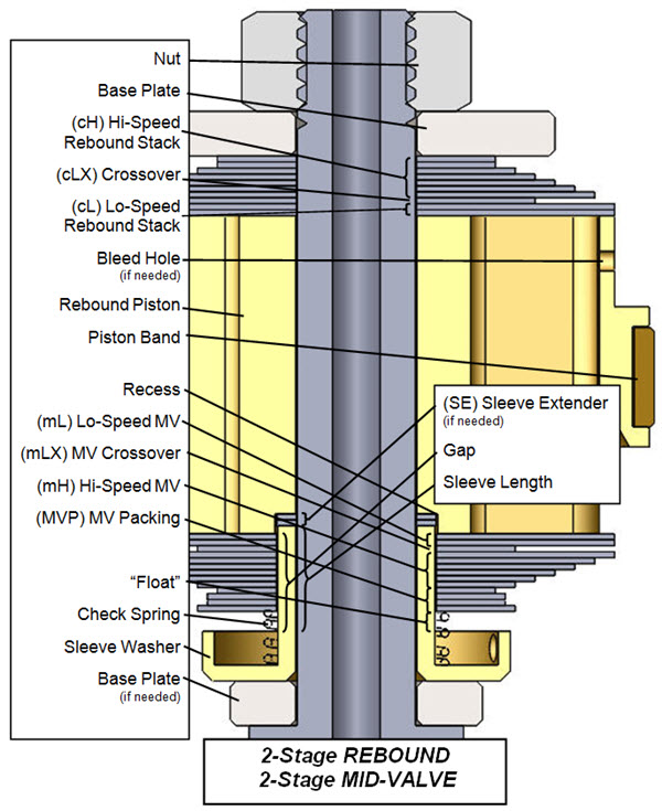
VP6- You will either be building a Single Stage or a Two Stage Stack. The difference is the Crossover. The Crossover is a smaller diameter shim between the Lo-Speed and the Hi-Speed Stacks. Note: The DVS Custom Setup Sheet displays individual shims and does not label Hi-Speed, Crossover, and Lo-Speed. This is for your information only. Also you will not use all the shims provided in the Gold Valve Kit.
|
|||||||
|
|
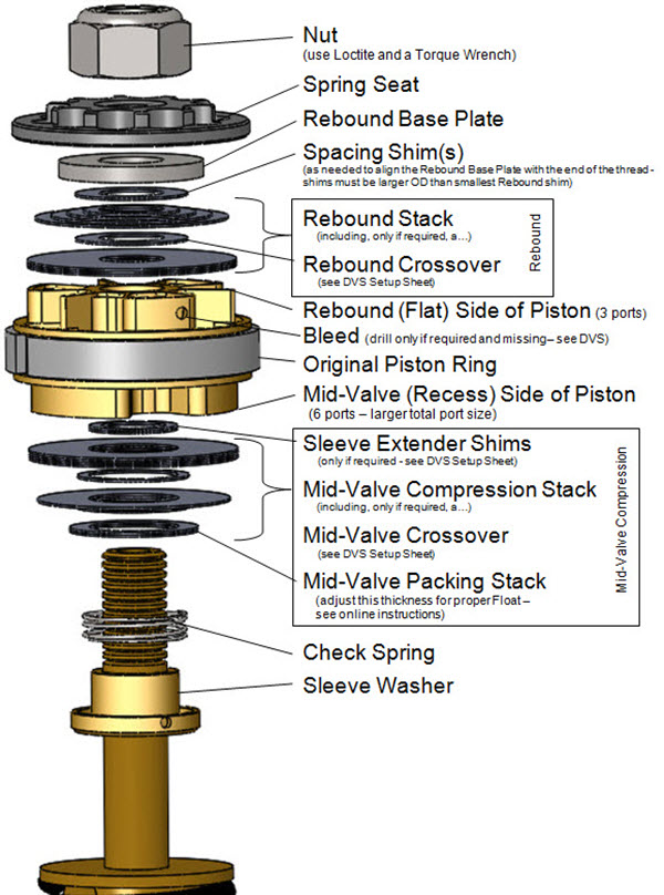
V7- MID-VALVE COMPRESSION STACK
First install the:
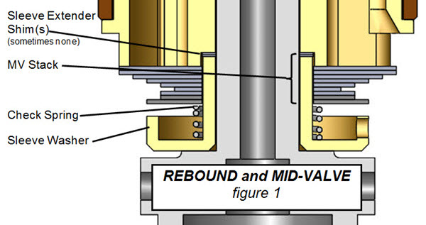
Sleeve Washer
Check Spring
Assemble the Mid-Valve Stack recommended by the DVS onto the Valving Shaft.
Note that on the DVS Setup Sheet it is listed from the piston face. This means it is in reverse order of assembly.
Note - there may be Sleeve Extender Shims (8 id x 11 od). Also there may be a Mid-Valve Crossover Shim.
Float is the amount the Mid-Valve stack moves before it has to bend. Float is critical!
Once the complete assembly is built, check the Float with a feeler gauge (step VR13). This may be off due to production tolerances on all of the parts in the assembly. Adjust the MV Packing Stack to create the correct Float.
|
||||||
|
|
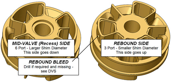
V8- REBOUND BLEED HOLE
The DVS Setup Sheet calls for a Rebound Bleed Hole. Check to see if there is one already pre-drilled in the piston. If one is called for, and there is no pre-drilled bleed hole, you will need to drill one.
Notice that the bleed hole is on the opposite side of the piston with the Recess and is drilled sideways. It connects the two sides of the piston and bypasses the valving stack. The exact location is not critical.
|
||||||
|
|
V9- Install the Rebound Gold Valve WITH THE RECESS IN THE GOLD VALVE FACING DOWN TOWARDS THE MID-VALVE.
|
||||||
|
|
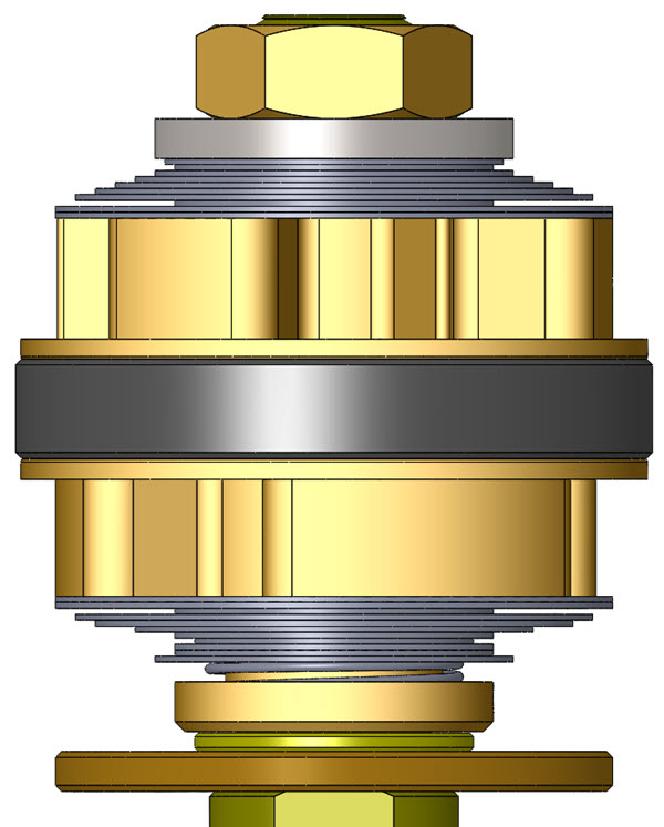
V10- REBOUND - Two Stage Example
Two Stage Stacks have a smaller diameter Crossover Shim in the stack. (Single Stage is exactly the same except there is no Crossover) (this is only an example - not your setting)
The Total Rebound Valving Stack starting from the Gold Valve piston face:
(4) .15x26
(1) .10x14 - Crossover (notice the smaller 14mm diameter)
(1) .10x26
(1) .10x24
(1) .10x22
(1) .10x18
(1) .10x16
(1) .10x14 (1) .10x12
Note: This is an example only! This valving stack shows the orientation of the components and the direction of the stack tapers.
|
||||||
|
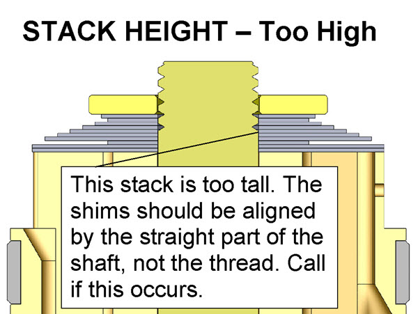
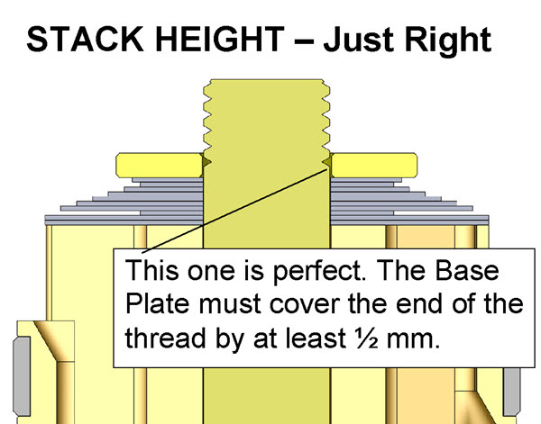
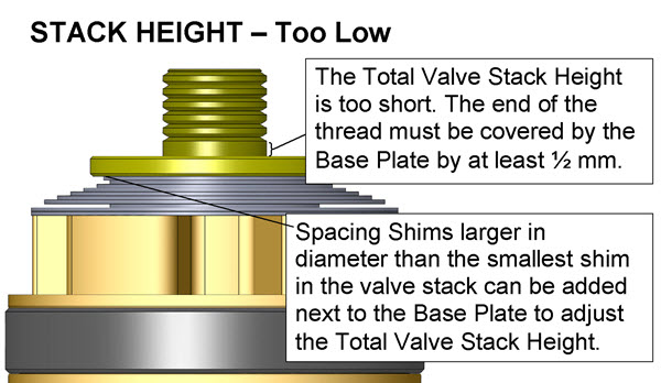
V11- Make sure the Total Valving Stack Height is correct. Critical!!
This step is here to insure you don't "run out of thread" onto the straight, non-threaded, portion of the shaft when tightening the Nut and the Nut gets full engagement.
The shims should be guided with the straight, non-threaded part of the shaft and should not be on the thread. The Rebound Base Plate or, in this case, Spring Seat should cover or "straddle" the end of the thread.
If needed, height adjustment is done with Spacing Shims added just below the Reboud Base Plate.
Spacing Shims must be larger in diameter than the smallest shim in the stack. Sometimes this is best accomplished by adding additional Base Plates.
NOTE: This kit is different than the images shown on the left as it includes a Sping Seat. The Spring Seat is placed on top of the Base Plate and can be thought of as the Base Plate in the images.
|
||||||
|
|
V12- TIGHTEN THE COMPLETE ASSEMBLY
Make sure there is Loctite on the thread of the shaft. Make sure the mid-valve is free to move up and down. Tighten it to spec with a torque wrench.
CAUTION! The threads can be damaged without extreme care. You must use Loctite.8mm bolts must be torqued with a torque wrench to 45 in-lbs (3.8 ft-lbs or 0.52 kgf-m), NO MORE! Check your DVS Setup Sheet. Do not take this step lightly. |
||||||
|
|
V13- CHECK THE FLOAT
(if you would like more detail about float click here) Float is the amount the stack moves before it has to bend.
FLOAT is the most critical valving setup in the entire front fork. Use a feeler gauge to measure the actual "float" of the mid-valve.
Insert the feeler gauge between the Gold Valve Piston face and the first shim. Make sure the feeler gauge goes all the way in to the surface of the inner sleeve.
This is the best way to check the float as there are always production tolerances that will throw the predicted float off of the calculated number.
Adjust the Sleeve Extender or Packing Stack (the last shims closest to the Check Spring) to get the correct float. THIS IS CRITICAL!
|
||||||
| V14- Single Stage Rebound and Single Stage Mid-Valve |
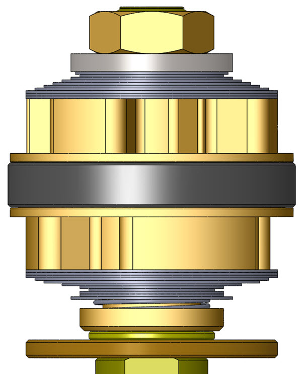
V14- Two Stage Rebound and Two Stage Mid-Valve |
||||||
|
|
V15- Check your work. Hold the valve assembly up to the light and look for proper assembly. If there are any problems, disassemble the stack and look for burrs to surface and/or dirt in the valving. Reassemble and check again.
|
||||||
|
|
V16- Make sure the shims that go next to the Gold Valve completely cover the ports on both sides of the piston! If the ports are not covered there will not be enough damping.
This could be caused by a number of reasons. Please call Tech Support if this occurs and you can't figure it out.
|
||||||
|
|
A1- ASSEMBLY
Check the Fork Spring Preload. Make sure the stock Preload Spacers are removed from the bottom of the Fork Tube. If they are not removed the Valving assembly will hit the Internal Reservoir.
Install the Reservoir Assembly into the chrome Inner Fork Tube first. The Reservoir comes pressurized to 5 psi. Insert the Fork Spring and lightly rest the Compression Damping Rod Assembly on the Fork Spring.
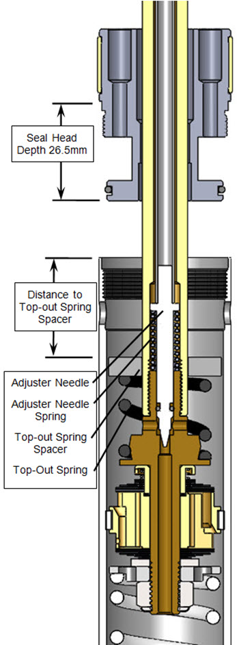
Take the Seal Head Depth (26.5mm) and subtract (the distance from the end of the chrome Inner Fork Tube down to the Top-out Spring Spacer). This is the Preload. It should be 3 to 4mm.
Preload = (26.5) - (Distance to Top-out Spring Spacer)
|
||||||
|
|
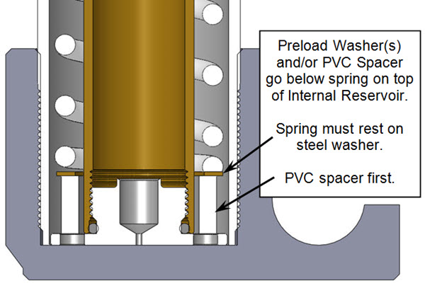
A2- If the Preload calculates out to be negative or just not enough, add Preload Spacers and Washers below the Spring over the Reservoir Tube. A 10mm long plastic spacer is included as it is commonly required. The Spring should rest on a steel washer not directly on the plastic spacer. Repeat with the Rebound (right) leg.
|
||||||
|
A3- Install the Dust Seal, Seal Clip and Oil Seal along with the Seal Washer and Outer Bushing on the Inner Fork Tube. (Note that the Seal Washer probably has been bent into a conical shape on disassembly. If you reverse the washer it will flatten itself during assembly.)
A4- With the Reservoir and Spring in, fill the Cartridge with Ultra Slick USF05. Insert the Damping Rod Assembly and stroke it up and down a few times until it is bled. Add Oil up to the bottom of the holes near the top of the Inner Tube. Slowly install the Seal Head, letting the oil overflow into the gap between the Inner and Outer Fork Tube. This procedure completely fills the damping chamber. Use Loctite and torque the Seal Head to 40 ft-lbs.
A5- Install the Outer Fork Tube and use a Seal Driver to insert, first the Bushing and, then the Oil Seal into the Outer Tube. Install the Seal Clip and the Dust Seal.
A6- Insert the Adjusting Rod down the center of the Damping Rod. Install the plastic Bottom-out Sleeve.
A7- The Adjuster threads into the Damping Rod, not the Cap. Screw the Adjuster into the Damping Rod. Use Loctite on the damping rod thread at the cap. Screw the Cap onto the Damping Rod until it gently bottoms. Tighten the Jam Nut onto the Cap. Set the Adjuster to the DVS recommended setting.
A8- Add fork oil to the outer chamber according to the DVS. Set the Air Pressure in the “Air Only” leg.
A9- When the forks are put on the bike it is very important to align the fork tubes. This is done by first tightening the axle all the way, then the tubes are aligned by pumping the forks up and down with the axle clamp loose. This will line the tubes up so they won't bind. Finally, tighten the axle clamp.
|
|||||||
| • Single Stage - made of: Lo-Speed Stack Hi-Speed Stack There is NO Crossover |
 |
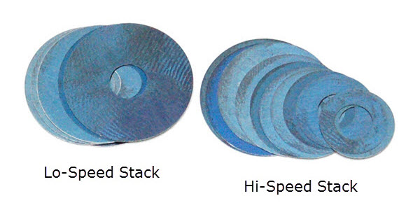 |
| • Two Stage - made of: Lo-Speed Stack Crossover Hi-Speed Stack The Crossover Gap is visible |
 |
 |


