FORK COMPRESSION
|
|||||||
|
|
Tools Required
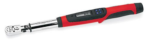
- In-lb torque wrench that accurately measures 0 to 50 in-lbs (0.58 kgf-m) (SnapOn Digital Torque Wrench shown)
- Hi-Strength Loctite (included)
- Metric calipers and micrometer
|
||||||
| There are two types of Compression Base Assemblies: 1. Valving Bolt Type - Bolt comes in from the top (continue with these instructions) and 2. Valving Post Type - Post comes in from the bottom (ClickHere)
Click image to enlarge. |
|||||||
EXAMPLES: |
|||||||
|
|
|
||||||
2. Valving Bolt - from the top |
|||||||
|
|
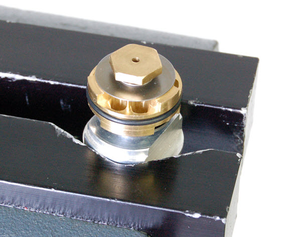
VB1- The Compression Base Valve may come pre-assembled. Disassemble it to check and change valving. Hold the Compression Base in the "V" of TMVJ 065 Vise Jaws.
|
||||||
|
|
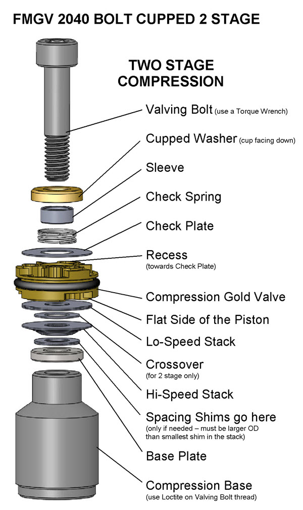
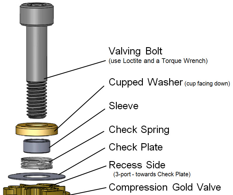
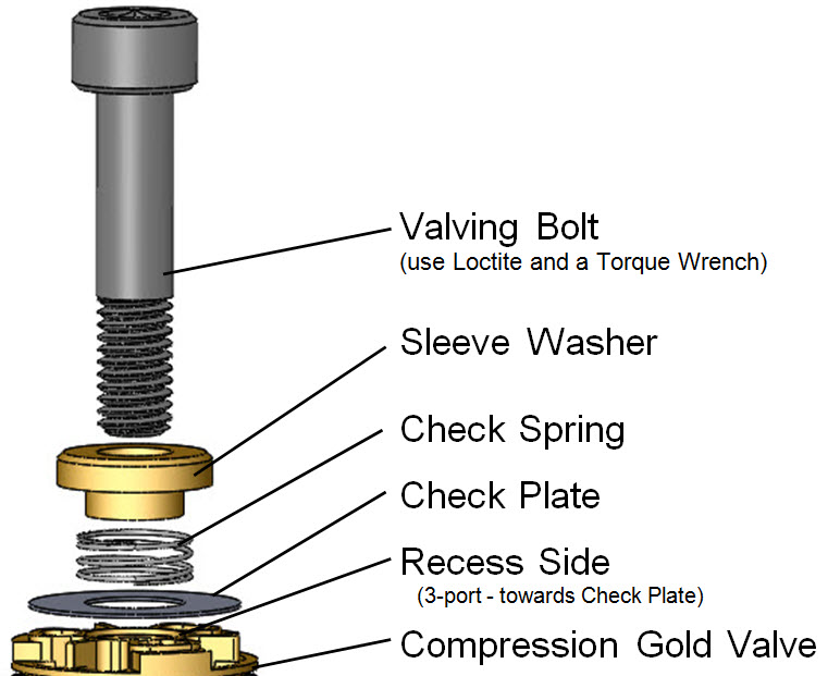
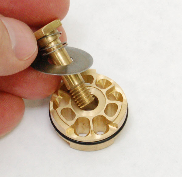
VB2a- Hardware variations:
1- Valving Bolt, Cupped Washer, Sleeve, Check Spring and Check Plate.
|
||||||
|
|
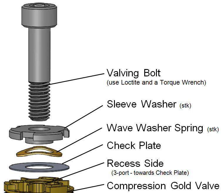
VB2b-
or
2- Valving Bolt, Sleeve Washer, Check Spring and Check Plate.
(This type could also use a Wave Washer instead of a coil spring.)
|
||||||
|
|
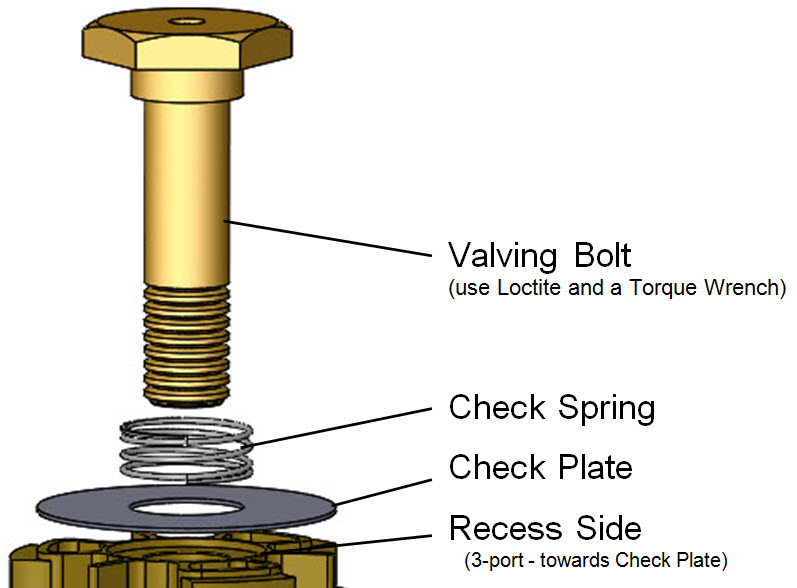
VB2c-
or
3- Valving Bolt, Check Spring and Check Plate.
|
||||||
|
|
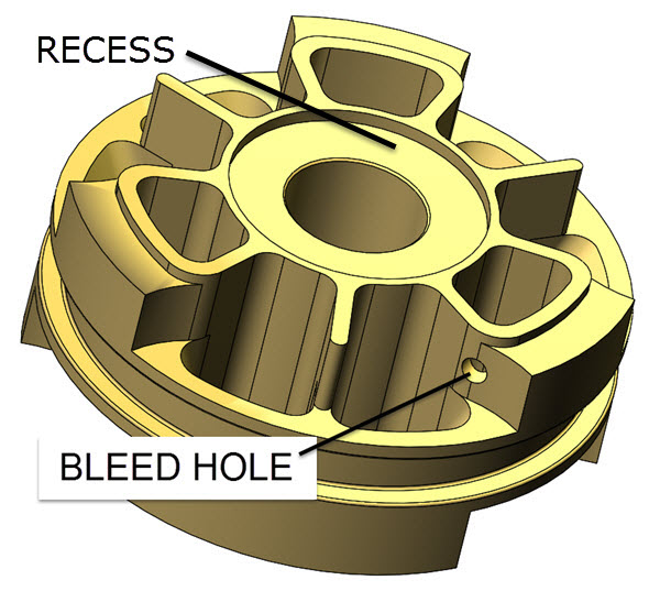
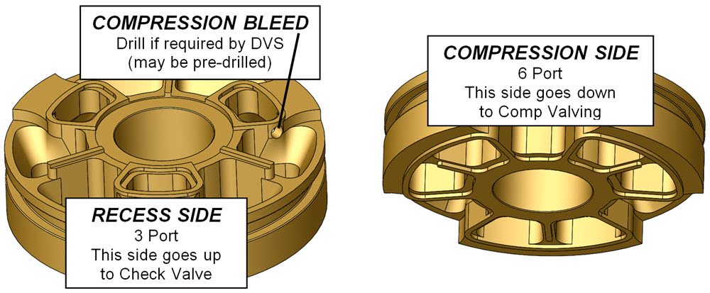
VB3- COMPRESSION BLEED HOLE
If the DVS does not call for a Compression Bleed Hole skip this step.
If your DVS Setup Sheet calls for a Compression Bleed Hole check to see if it is already pre-drilled in the piston. If it is not you will need to drill one.
Notice that the bleed hole is on the side of the piston with the recess and is drilled sideways. It connects the two sides of the piston and bypasses the valving stack. The exact location is not critical.
|
||||||
|
|
VB4- The two sides of the Gold Valve are different. It is important to orient it properly. Place the Gold Valve on the shaft with the Recess going on to the bolt first.
The Recess is the circular pocket on the top face of the Gold Valve Piston.
|
||||||
|
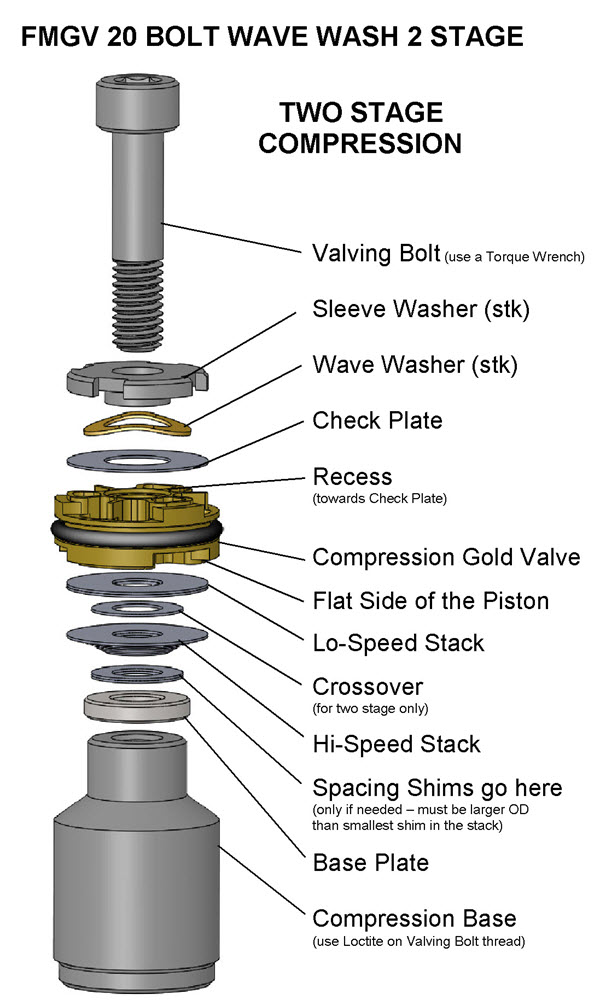
VALVING STACK TYPES - SINGLE OR TWO STAGE
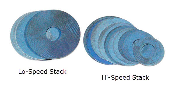
VB5- You will either be building a Single Stage or a Two Stage Stack. The difference is the Crossover. The Crossover is a smaller diameter shim between the Lo-Speed and the Hi-Speed Stacks. Note: The DVS Custom Setup Sheet displays individual shims and does not label Hi-Speed, Crossover, and Lo-Speed. This is for your information only. Also you will not use all the shims provided in the Gold Valve Kit.
|
|||||||
|
|
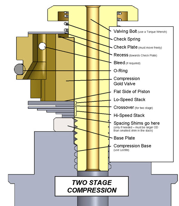
VB6- Two Stage Example
(Single Stage is exactly the same except there is no Crossover) Put the valving on the shaft in the order listed, starting with the Lo-Speed Stack.
For Two Stage the total valving stack is made up of a:
Lo-Speed Stack
Crossover and a
Hi-Speed Stack
(this is only an example - not your setting)
The Total Valving Stack starting from the Gold Valve piston face:
(4) .15x17 - Lo-Speed Stack
(1) .10x11 - Crossover (notice the smaller diameter)
(1) .10x17 - Hi-Speed Stack
(1) .10x16
(1) .10x15
(1) .10x14
(1) .10x13
(1) .10x12
(1) .10x11
(1) .10x10
|
||||||
|
|
VB7- Place the Base Plate (thick washer) on the shaft.
There are models that require 2 Base Plates.
Notice that the Valving Bolt is being held into the Recess. This keeps the Check Plate aligned during assembly.
|
||||||
|
|
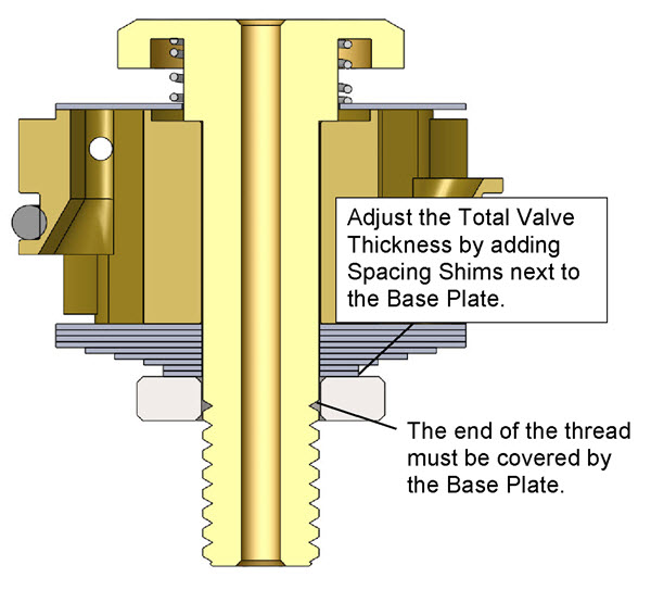
VB8- Make sure the Total Valving Stack Height is correct.
This step is here to insure you don't "run out of thread" when tightening the Valving Bolt. This height adjustment is done with Spacing Shims. If needed, they should be added just above the Base Plate. Spacing Shims must be larger in diameter than the smallest shim in the stack
The shims should be guided with the straight, non-threaded part of the shaft and should not be on the thread so the thread should be covered by the Base Plate.
When the valve stack is compressed during installation, the thread cannot extend below the Base Plate too.
|
||||||
|
|
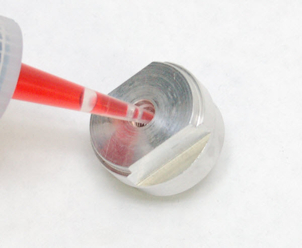
VB9- Use Loctite on the Compression Base thread...
|
||||||
|
|
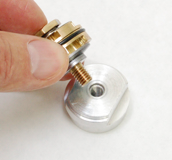
VB10- make sure the Base Plate is installed, then install the Valving Bolt and...
|
||||||
|
|
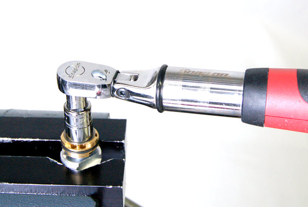
VB11- tighten it to spec with a torque wrench.
CAUTION! The threads can be damaged without extreme care. You must use Loctite. The 6mm bolt must be torqued with a torque wrench to the setting in the DVS. Do not take this step lightly. |
||||||
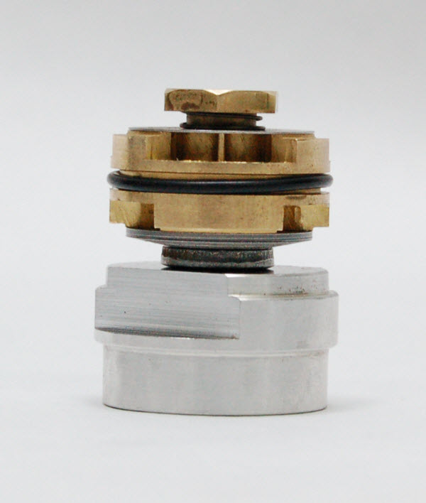
| VB12- Single Stage
|
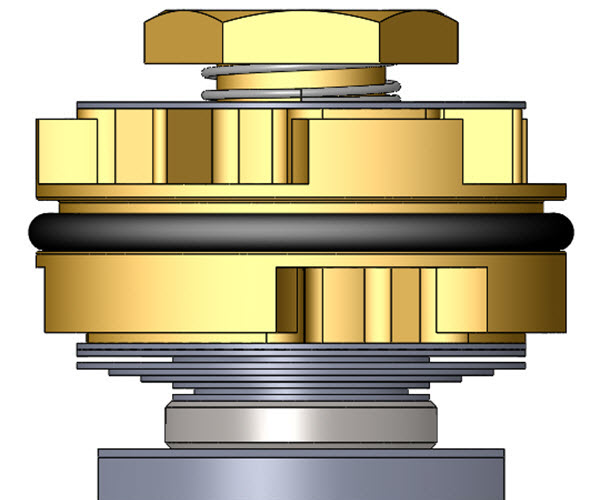
VB12- Two Stage
|
||||||
|
|
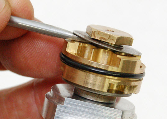
VB13- Make sure the Check Plate is free and can move up and down against the Spring.
|
||||||
|
|
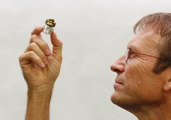
VB14- Visually check your work.
Hold the Compression Stack up to the light and look for proper assembly. If there are any problems, disassemble the stack and look for burrs to surface and/or dirt in the valving. Reassemble and check again.
Make sure the o-ring is on the Gold Valve.
Make sure the o-ring is on the Gold Valve. Some kits contain more than one o-ring. See your DVS Setup Sheet Valving Comments for the correct o-ring.
|
||||||
|
|
VB15- Make sure the shims that go next to the Gold Valve completely cover the ports on both sides of the piston! If the ports are not covered there will not be enough damping.
This could be caused by a number of reasons. Please call Tech Support if this occurs and you can't figure it out.
|
||||||
|
VB16- Return to the main instructions and continue with Rebound Valving and Assembly.
|
|||||||
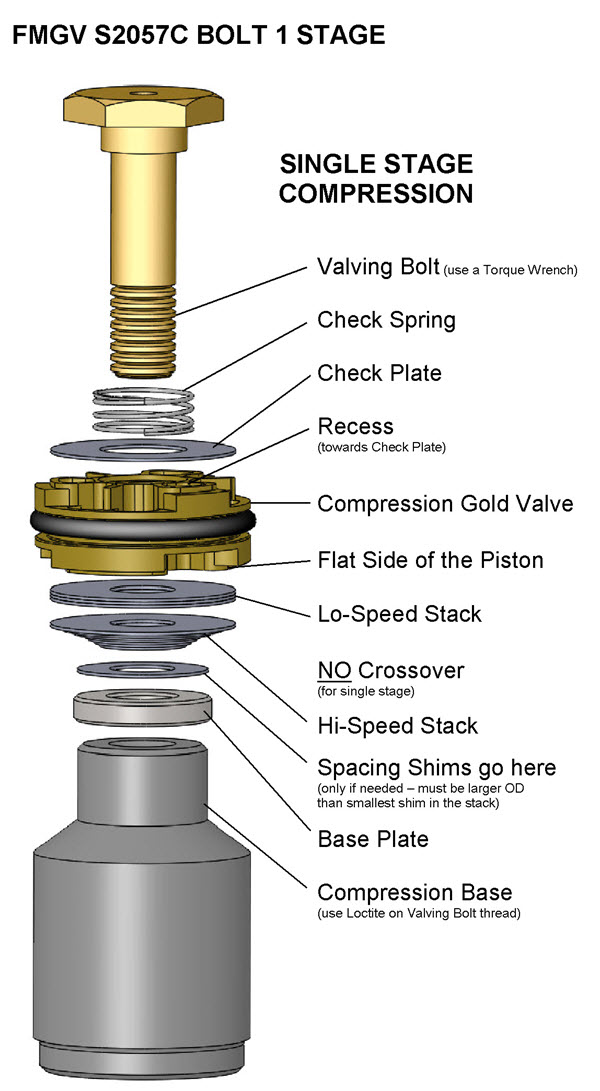
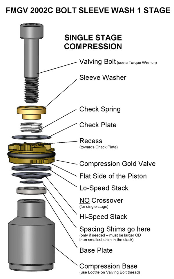
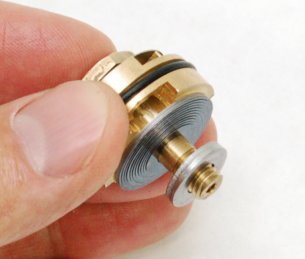
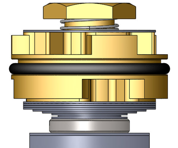
| • Single Stage - made of: Lo-Speed Stack Hi-Speed StackThere is NO Crossover (it becomes one stack.) |
 |
 |
| • Two Stage - made of: Lo-Speed Stack Crossover Hi-Speed StackThe Crossover Gap is visible |
 |
 |