FORK COMPRESSION
|
|||||||
| Welcome to the wonderful world of Gold Valving. To obtain your personal Custom Suspension Settings:
For general fork rebuild procedure refer to the Fork Gold Valve Instruction List. CAUTION: IF YOU ARE UNFAMILIAR WITH REBUILDING AND REVALVING FORKS, STOP!!! DO NOT PROCEED; SEEK OUT A QUALIFIED SUSPENSION TECHNICIAN. NOTE: All measurements are metric (for inches divide by 25.4). The valving list starts at the piston face and goes towards the Base Plate. Valve specs are listed by (QUANTITY) THICKNESS x DIAMETER. A number in parentheses means quantity. If there is no number in parenthesis the quantity is one. Example: (2).15x30 means quantity two, 15 hundredths of a millimeter thick by 30 millimeters in diameter. |
|||||||
|
|
Tools Required
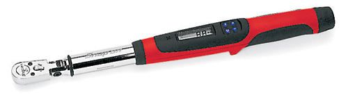
- In-lb torque wrench that accurately measures 0 to 50 in-lbs (0.58 kgf-m) (SnapOn Digital Torque Wrench shown)
- Hi-Strength Loctite (included)
- Metric calipers and micrometer
|
||||||
| There are about four styles of compression holders. There are a few subtle hardware differences but are all very similar. | |||||||
|
|
|
||||||
|
|
VP1- Most Japanese forks like KYB and Showa have peening on the end of the shaft for nut retention insurance.
File the peening from the top of the compression shaft down to the top of the nut.
There are some models where the shaft is "staked". This means there are sharp notches instead of smooth peening. In this case be sure the notches are completely cleaned out.
Euro models like WP, Sachs, and Ohlins are not peened and don't require this step.
|
||||||
|
|
VP2- The shaft should be ground to the nut's surface. Once this is done, remove the nut and Valving Stack.
|
||||||
|
|
VP3- On peened type holders, slightly chamfer the end of the thread with a fine file. Do not be too aggressive as on some models there is not much thread.
If you blow it and mess up the thread please call us as we may have a solution available.
Dressing the end with a wire wheel makes it very clean.
|
||||||
|
|
VP4- Blow air through one of the side holes while covering up the other side hole. This blows out fillings. Use contact cleaner and repeat.
|
||||||
|
|
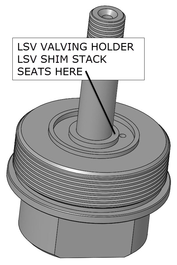
VP5- Install the LSV Stack and the Base Plate on the Shaft.
Note the largest diameter shim goes on the shaft first.
There are models that require 2 or even 3 Base Plates to create the correct Total Valve Stack Height. See step VP11.
There are some valving stacks that do not completely cover the seat. This disables the LSV and converts it to a conventional adjustable bleed. See your DVS Setup Sheet and the image below.
|
||||||
|
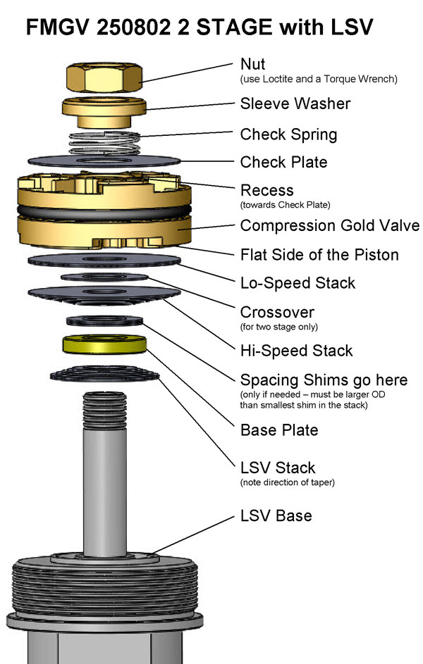
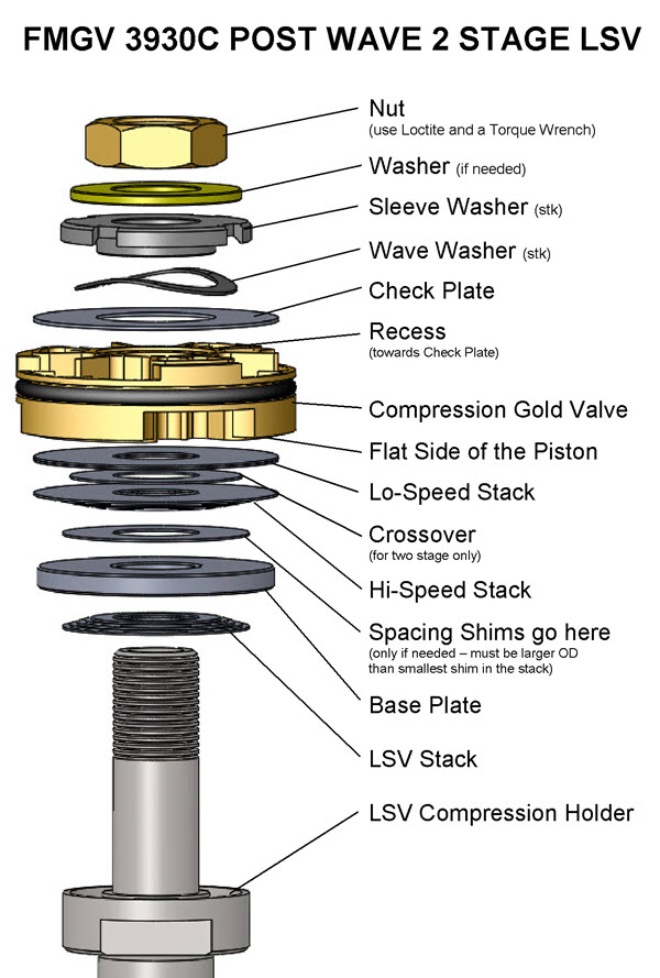
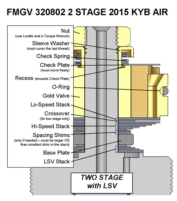
VALVING STACK TYPES - SINGLE OR TWO STAGE
VP6- You will either be building a Single Stage or a Two Stage Stack. The difference is the Crossover. The Crossover is a smaller diameter shim between the Lo-Speed and the Hi-Speed Stacks. Note: The DVS Custom Setup Sheet displays individual shims and does not label Hi-Speed, Crossover, and Lo-Speed. This is for your information only. Also you will not use all the shims provided in the Gold Valve Kit.
|
|||||||
|
|
VP7- Two Stage Example
(Single Stage is exactly the same except there is no Crossover) Put the valving on the shaft in the reverse of the order listed, starting with the last (smallest) shim of the Hi-Speed Stack.
For Two Stage the total valving stack is made up of a:
Lo-Speed Stack
Crossover and a
Hi-Speed Stack
(this is only an example for a 20mm piston to show the direction of the taper - not your setting)
The Total Valving Stack starting from the Gold Valve piston face:
(4) .15x17 - Lo-Speed Stack
(1) .10x11 - Crossover (notice the smaller diameter)
(1) .10x17 - Hi-Speed Stack
(1) .10x16
(1) .10x15
(1) .10x14
(1) .10x13
(1) .10x12
(1) .10x11
(1) .10x10
|
||||||
|
|
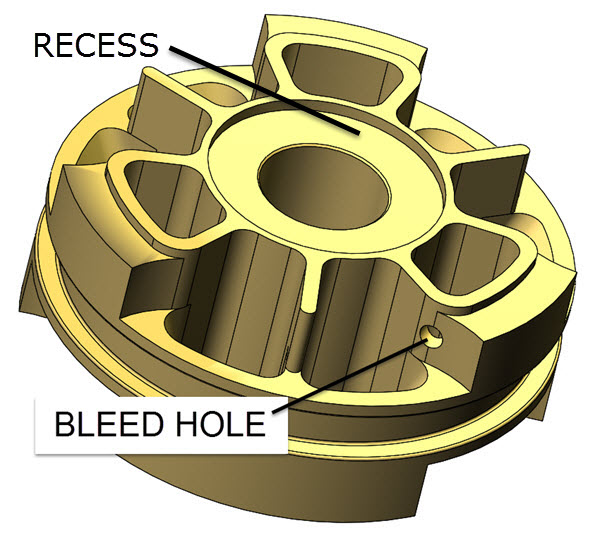
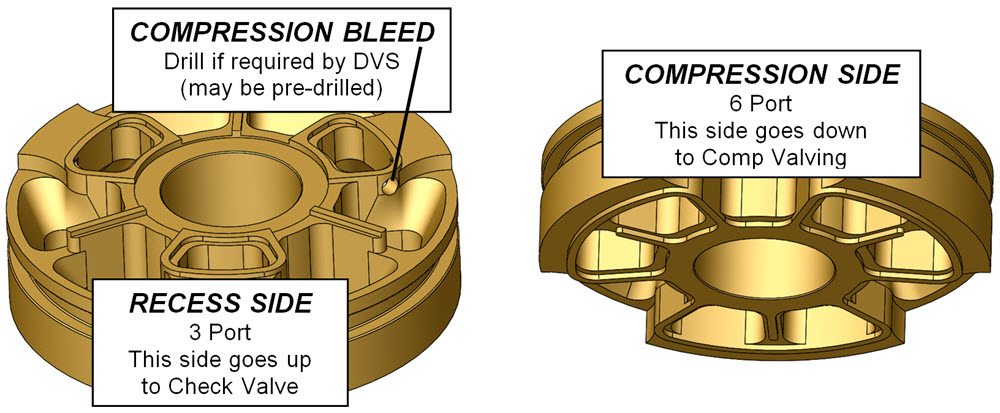
VP8- COMPRESSION BLEED HOLE
If the DVS does not call for a Compression Bleed Hole skip this step.
If your DVS Setup Sheet calls for a Compression Bleed Hole check to see if it is already pre-drilled in the piston. If it is not you will need to drill one.
Notice that the bleed hole is on the side of the piston with the recess and is drilled sideways. It connects the two sides of the piston and bypasses the valving stack. The exact location is not critical.
|
||||||
|
|
VP9- Install the Gold Valve. The recessed side goes up.
The Recess is the circular pocket on the top face of the Gold Valve Piston.
|
||||||
|
|
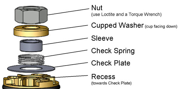
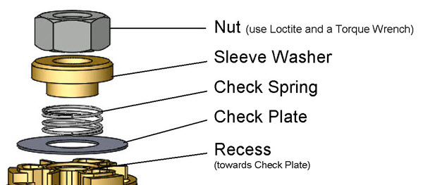
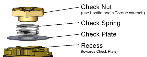
VP10- Place the Check Plate, Check Spring, and either:
1- Sleeve, Cupped Washer, and Nut
or
2- Sleeve Washer and Nut
(This type could also use a Wave Washer instead of a coil spring.)
or
3- Check Nut
on the Shaft.
|
||||||
|
|
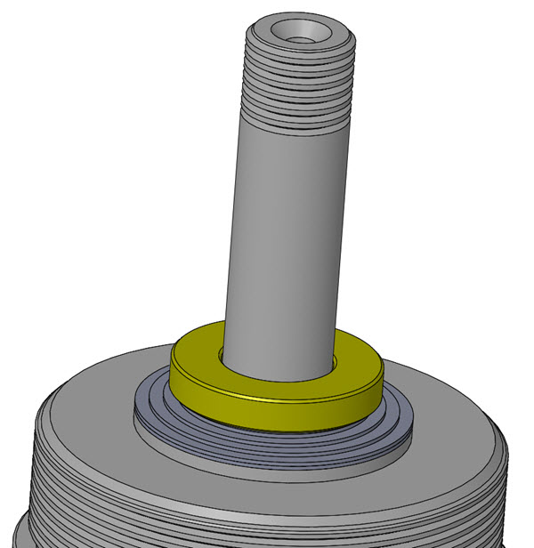
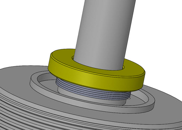
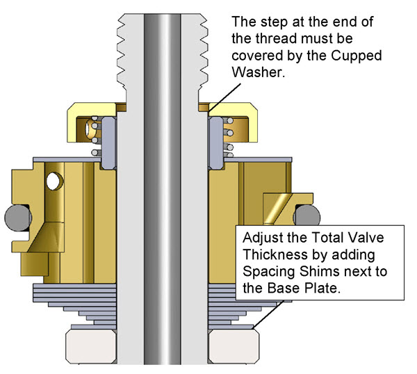
This step is here to insure you don't "run out of thread" when tightening the Nut and the Nut gets full engagement.
The shims should be guided with the straight, non-threaded part of the shaft and should not be on the thread so the thread should be covered by the Base Plate.
This height adjustment is done with Spacing Shims. If needed, they should be added just above the Base Plate. Spacing Shims must be larger in diameter than the smallest shim in the stack.
Click on the image to enlarge.
|
||||||
|
|
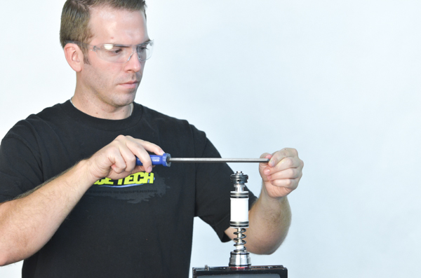
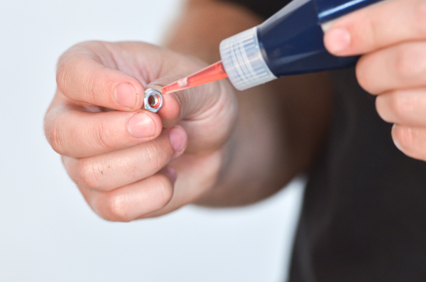
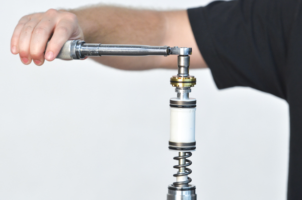
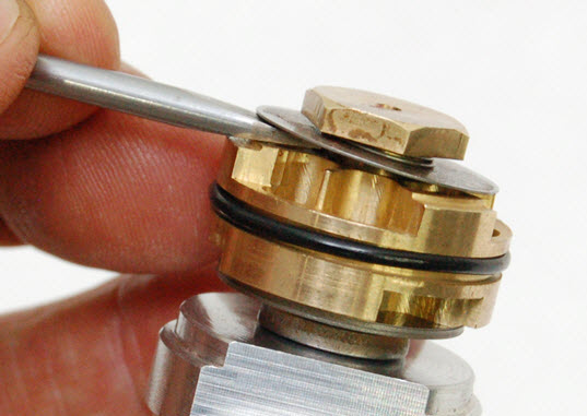
VP12- Apply a small drop of Loctite to the valving shaft nut.
|
||||||
|
|
VP13- Check to make sure the check valve is free before the nut is tightened.
|
||||||
|
|
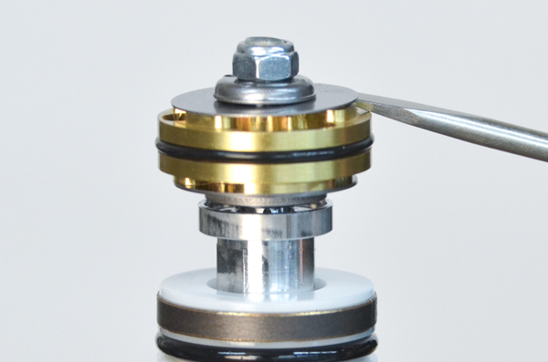
VP14- tighten it to spec with a torque wrench. CAUTION! The threads can be damaged without extreme care. You must use Loctite. Torque the Nut to the spec on your DVS Setup Sheet. NO MORE! Do not take this step lightly.This is critical! |
||||||
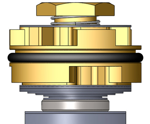
| VP15- Single Stage
|
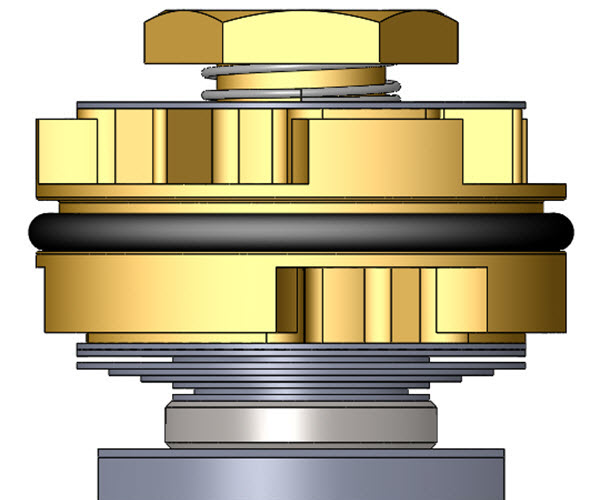
VP15- Two Stage
|
||||||
|
|
VP16- Make sure the Check Plate is free and can move up and down against the Spring.
|
||||||
|
|
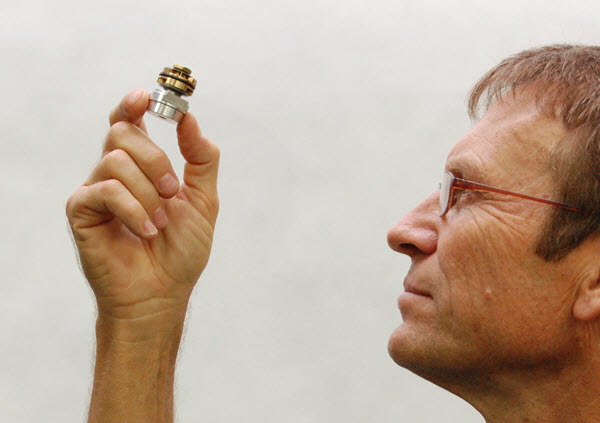
VP17- Visually check your work.
Hold the Valving Stack up to the light and look for proper assembly. If there are any problems, disassemble the stack and look for burrs to surface and/or dirt in the valving. Reassemble and check again.
On two-stage stacks make sure the Crossover Gap is clearly visible.
Make sure the o-ring is on the Gold Valve. Some kits contain more than one o-ring. See your DVS Setup Sheet Valving Comments for the correct o-ring.
|
||||||
|
|
VP18- Make sure the shims that go next to the Gold Valve completely cover the ports on both sides of the piston! If the ports are not covered there will not be enough damping.
This could be caused by a number of reasons. Please call Tech Support if this occurs and you can't figure it out.
|
||||||
|
VP19- Return to the main instructions and continue with Rebound Valving and Assembly.
|
|||||||


| • Single Stage - made of: Lo-Speed Stack Hi-Speed Stack There is NO Crossover |
 |
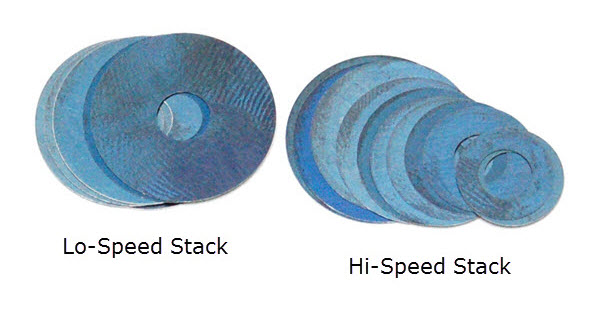 |
| • Two Stage - made of: Lo-Speed Stack Crossover Hi-Speed Stack The Crossover Gap is visible |
 |
 |