Fork Rebuild
|
|
|
|
Supplies
USF-05 Fork Oil - extremely slippery
Contact Cleaner - or other good, clean solvent
Fork Springs (likely - check the Product Search for rate recommendations)
Loctite - Hi Strength
|
|
|
Special Tools
TFCH 01 Cartridge Holding Tool - required
TFSC 01 Portable Fork Spring Compressor - very handy
or
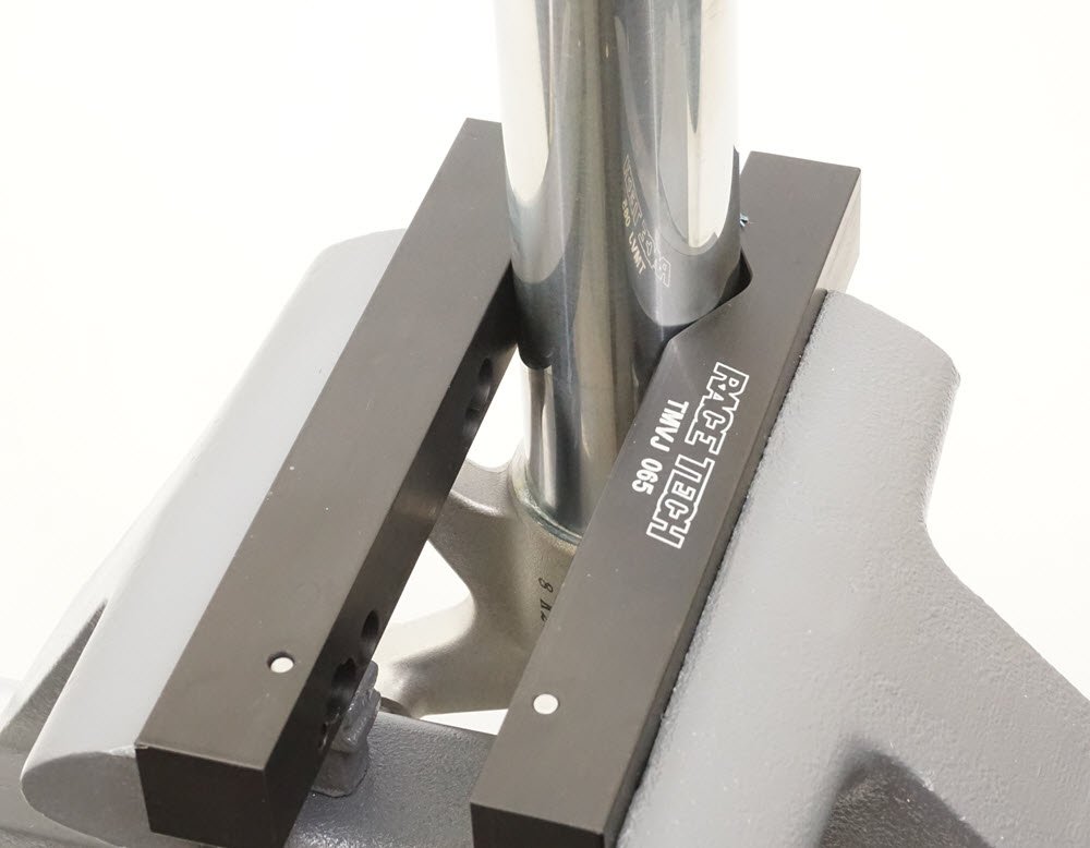
TMVJ 065 Vise Jaws mounted on a Vise - suggested
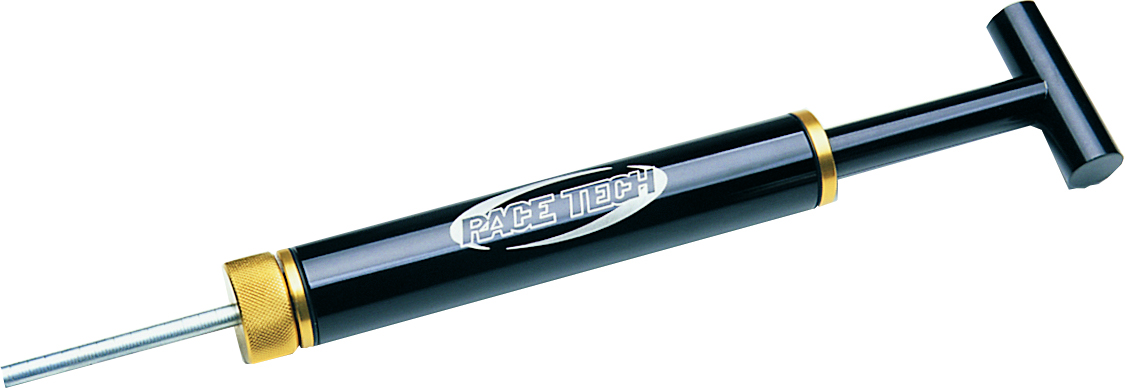
TFBT 10100 Bleeding Tool (optional) - suggested
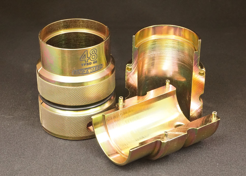
TFSD 41 or 43 Seal Driver (required if changing seals or bushings)
Wood Chisel (or sharp chisel)
TPSH 10 Shaft Holding Tool (included in Gold Valve Kit)
TFOL 02 Oil Level Tool - suggested
|
|
|
|
|
|
FD2- Back out the compression adjuster all the way.
|
|
|
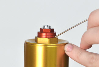
FD3- Check the position of the preload adjuster and note the height for future reference.
|
|
|
FD4- Back out the preload adjuster all the way.
|
|
|
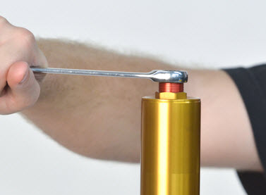
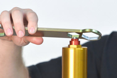
FD5- Remove the fork cap using a Fork Cap Wrench or appropriate socket.
|
|
|
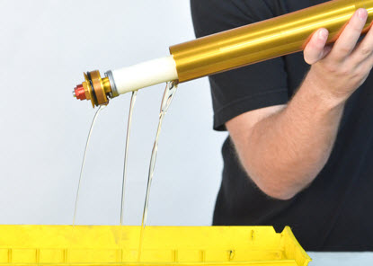
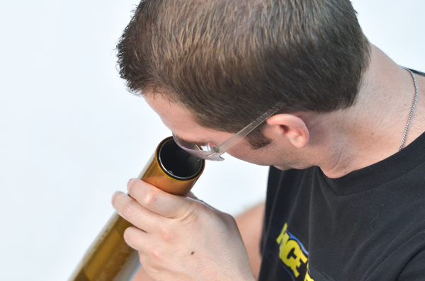
FD6- Drain the fork oil and dispose of properly.
|
|
|
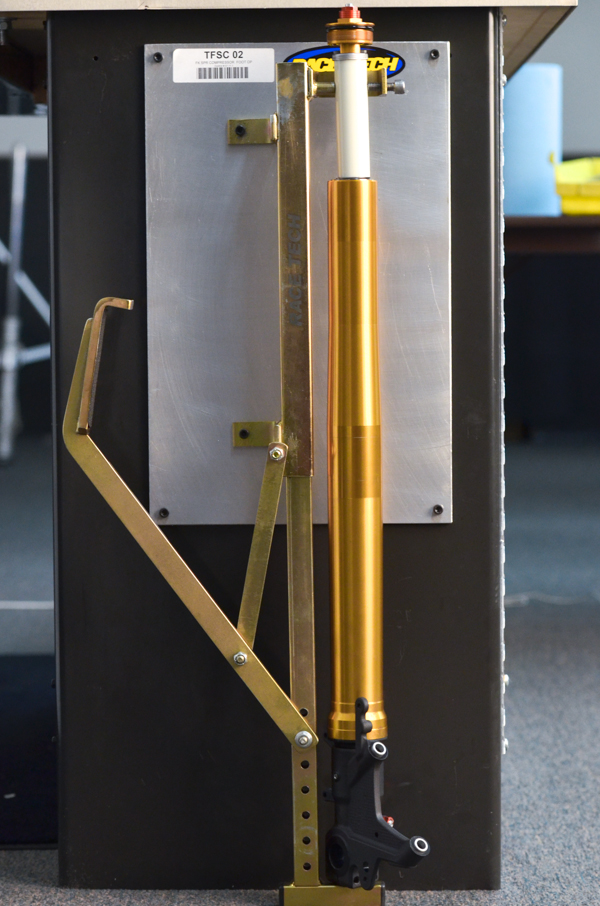
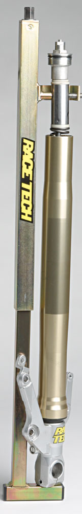
FD7- Wall Mounted Spring Compressor Option 1: Place the fork in a RT Fork Spring Compressor (TFSC 02) with the tool's top pins in the holes in the spring spacer and the locating pin in the bottom of the fork.
|
|
|
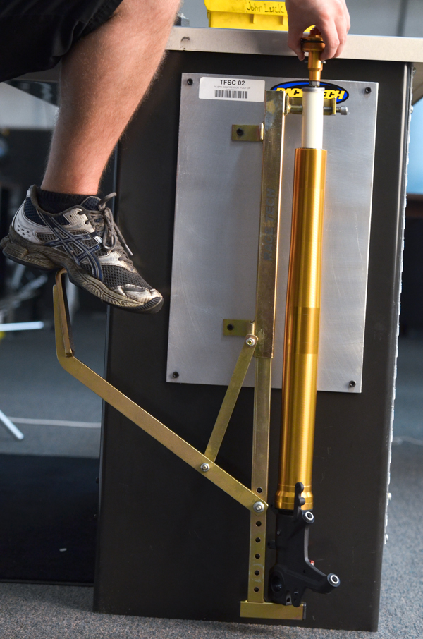
FD8- Compress the fork spring.
|
|
|
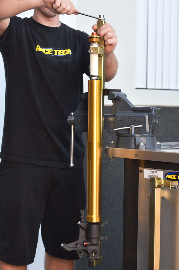
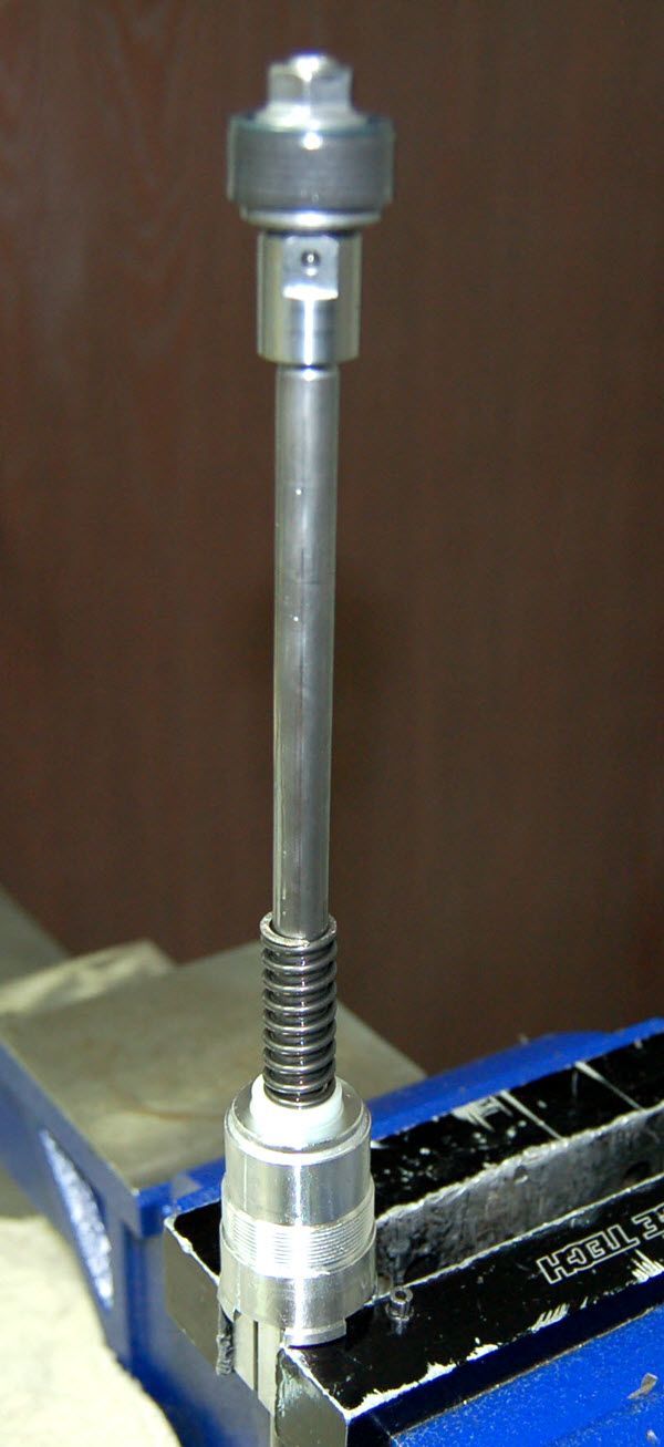
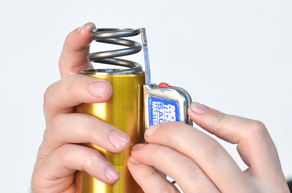
FD9- Portable Fork Spring Compressor Option 2: Clamp the Fork Spring Compressor in a vise and place the fork in RT Fork Spring Compressor (TFSC 01). Put the tool's top pins in the holes in the spring spacer and the locating pin in the bottom of the fork.
|
|
|
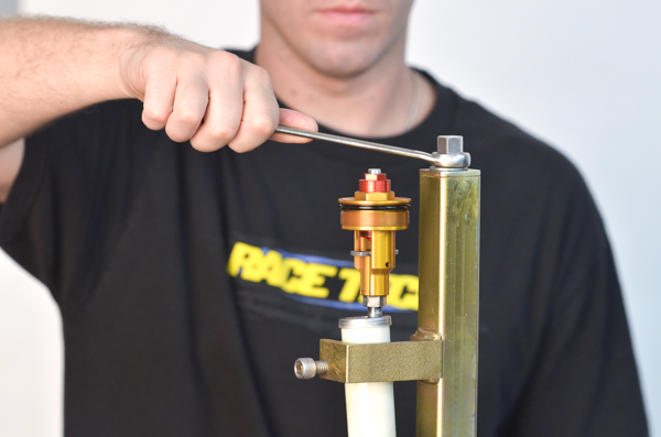
FD10- Using a wrench or socket (not an impact), tighten it down to compress the fork spring.
|
|
|
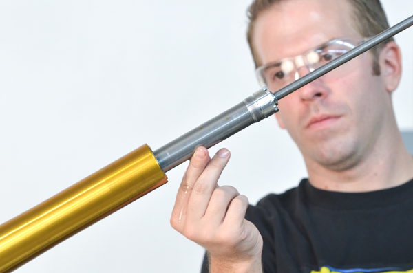
FD11- This will expose the Jam Nut on the Damping Rod. Loosen the fork cap from the damping rod.
You may have to lift up on the Fork Cap to separate it from the spacer.
|
|
|
FD12- Remove the fork cap.
|
|
|
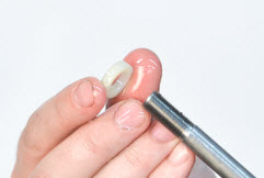
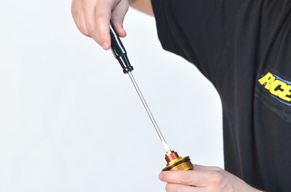
FD13- Remove the rebound adjusting rod in the center of the damping rod.
|
|
|
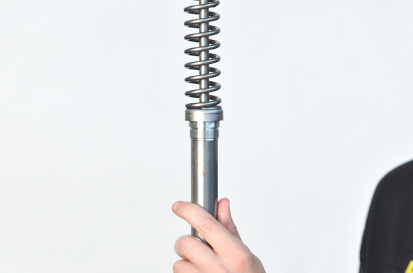
FD14- Remove the spring and the preload spacer.
|
|
|
FD15- Remove the bottom spring washer. Some oil will drain from the fork.
|
|
|
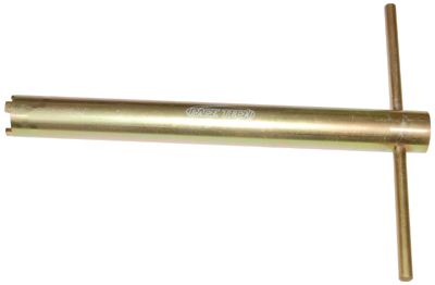
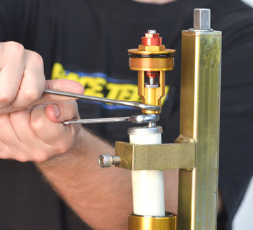
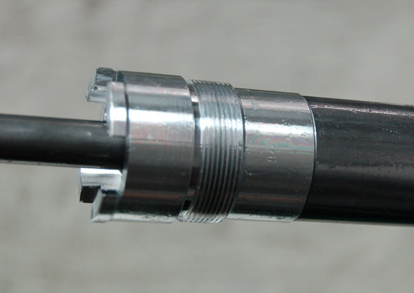
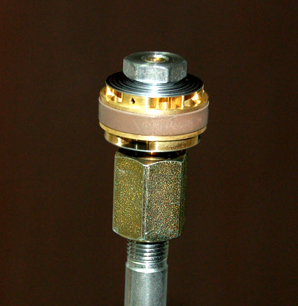
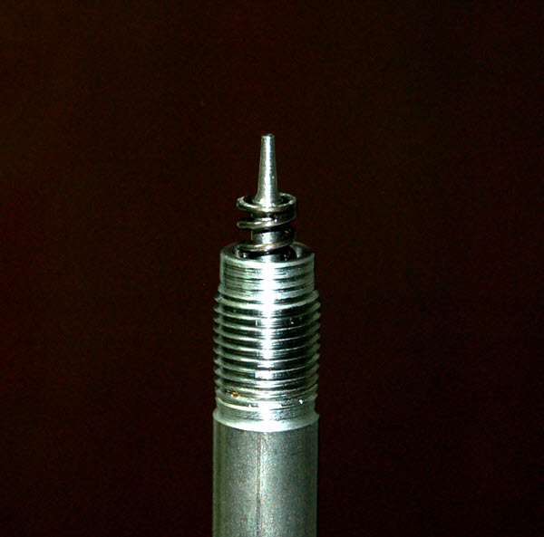
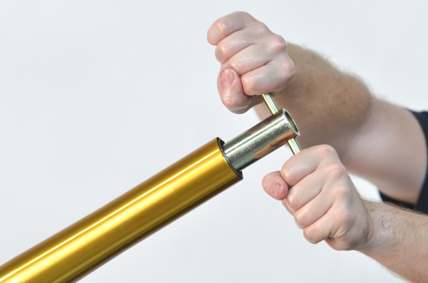
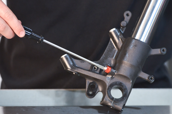
FD16- This fork design is a little different than most. The Cartridge screws into the bottom. This Cartridge Holding Tool (TFCH 01) is required on this model.
Insert the TFCH 01 Cartridge Holding Tool into the fork and make sure it registers into the slots properly.
The Fork Bottom should be firmly clamped in the soft jaws of the vise.
|
|
|
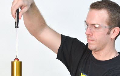
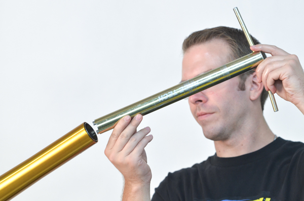
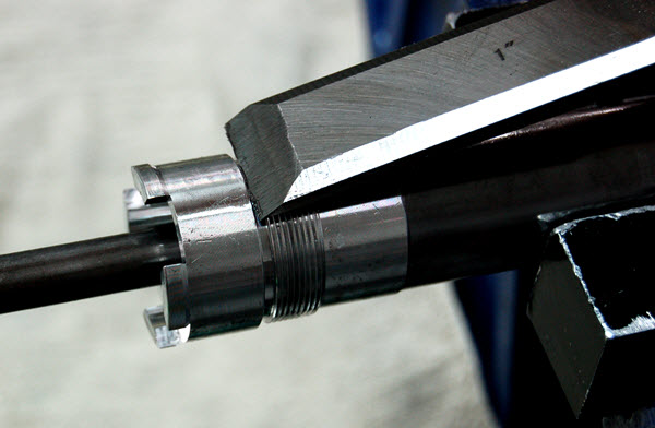
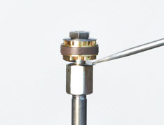
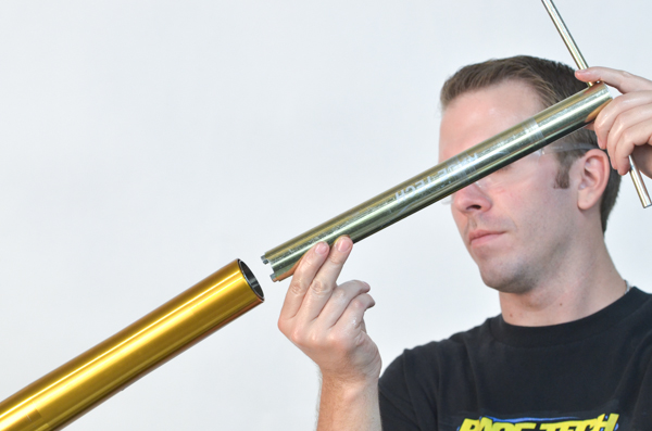
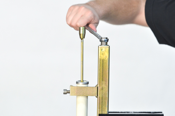
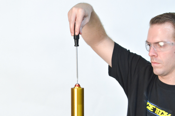
FD17- Unscrew the cartridge all the way.
Note - I prefer to do this with the fork held vertically but I think A.J. wanted to make sure he had a full frontal shot of his face.
|
|
|
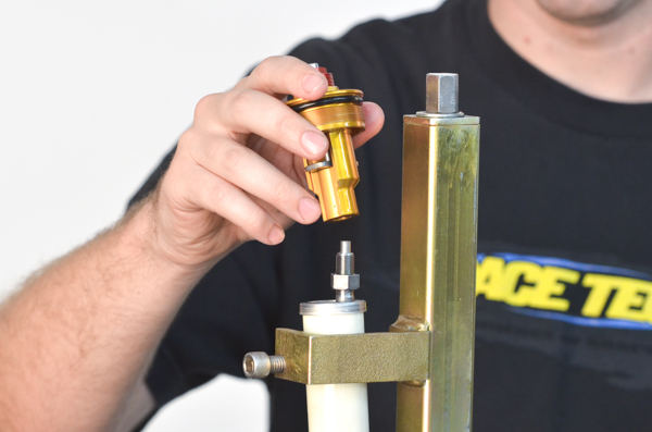
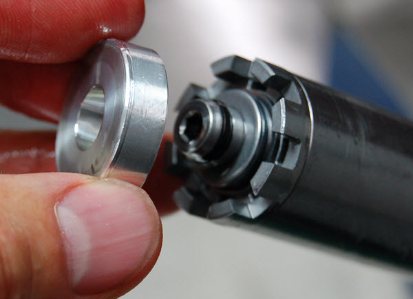
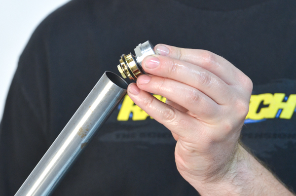
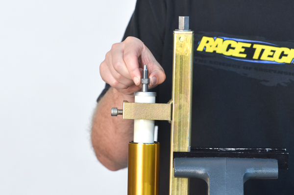
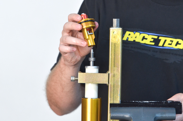
FD18- Remove the cartridge from the fork.
|
|
FD19-
|
|
|
|
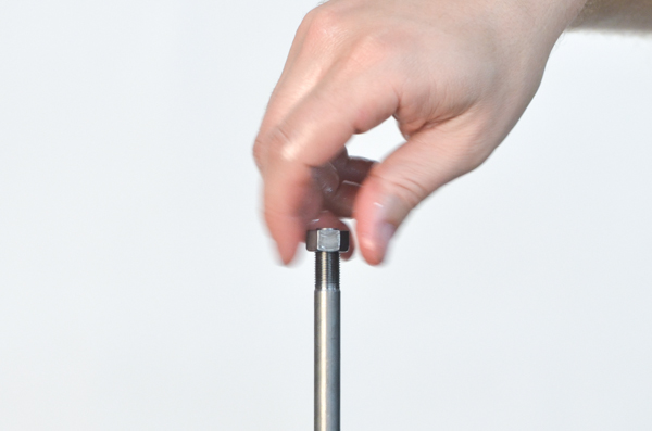
FD20- Remove the jam nut from the damping rod.
|
|
|
CD1-
Click here if you are interested in instructions on how to Remove the Bottom-out Piston (Not Required for Gold Valve Installation)
|
|
|
CD2-
|
|
CD3- The Seal Head along with the Rebound Valve Assembly can be slid out of the Cartridge Tube.
|
|
|
|
CD4-
|
|
|
CD5-
|
|
|
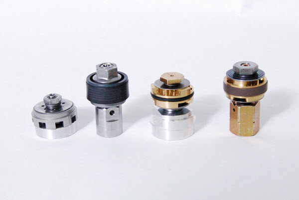
VC1- Left to right; the stock Compression Base Valve Assembly, stock Rebound Assembly, Compression and Rebound Gold Valve Assemblies.
|
|
|
|
|
|
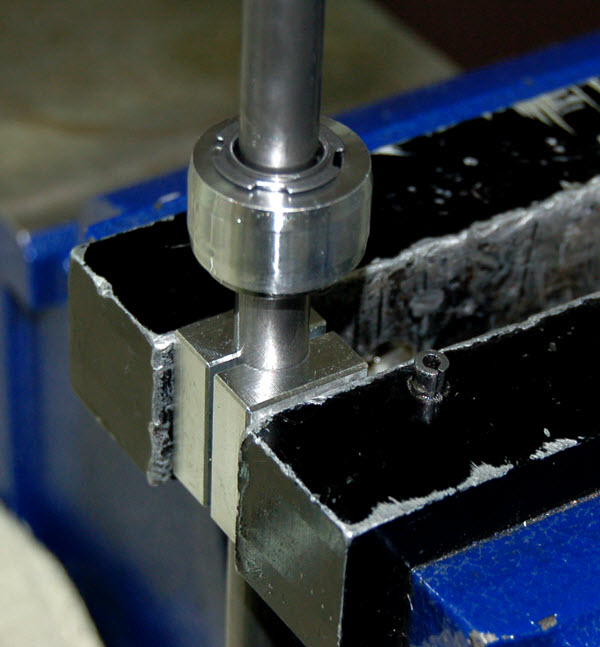
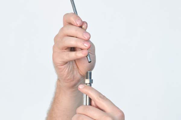
VR2- Very firmly clamp the damping rod below the Bottom-Out Piston in the Shaft Holding Tool provided.
Notes - Clamping tightly is good as the shaft is strong and there will only be damage if the rod spins in the tool.
Clamping below the Bottom-out Piston means that even if the shaft spins and creates surface damage it will not be in an area that matters.
|
|
|
VR3-
|
|
|
VR4-
|
|
VR5-
|
|
|
VR6-
|
|
|
|
VR7- Double check that the Rebound Check Valve opens freely.
|
|
|
|
|
CA2-
|
|
|
|
CA3-
|
|
|
CA4-
|
|
CA5-
|
|
|
CA6-
|
|
|
|
|
|
|
FA2- These pics show how the lower Spring Seat is installed. It rests on the seal head loosely with the cup facing downwards.
 |
|
|
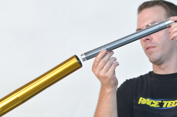
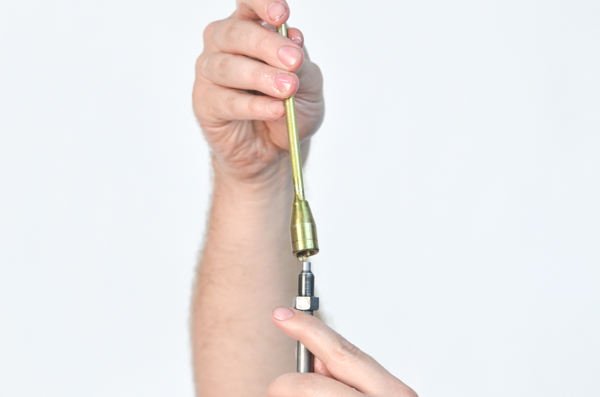
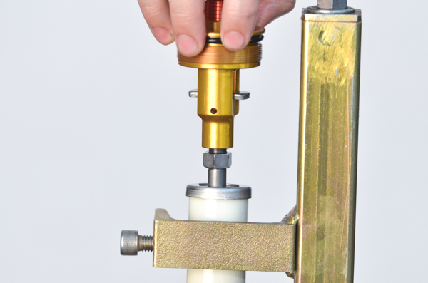
FA3- Insert the catrtidge assembly into the tube.
|
|
|
FA4- Insert the Cartridge Holding Tool. Make sure it locates into the notches in the top of the seal head.
|
|
|
FA5- Tighten firmly.
|
|
|
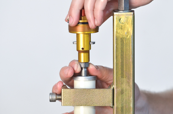
FA6- Insert the lower Spring Seat cupped side down.
|
|
|
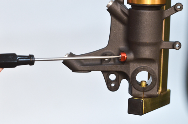
FA7- Visually inspect for the proper location of the Spring Seat.
|
|
|
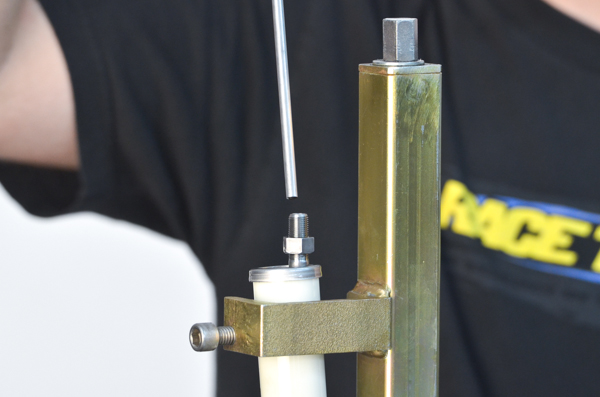
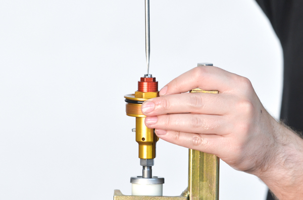
FA8- Screw the Bleeding Tool onto the end of the Damping Rod.
|
|
|
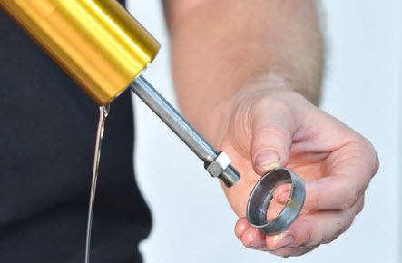
FA9- Use USF-05 Fork Oil and fill to about 50mm (2") from the top with the Outer Fork Tube completely collapsed.
(Notice the proper display of the Ultra Slick USF-05 bottle - good job A.J.!)
|
|
|
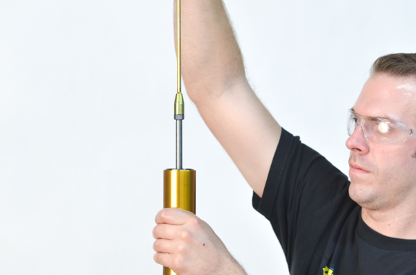
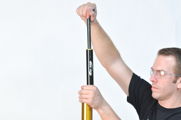
FA10- Stroke the Damping Rod until there are no air bubbles and...
|
|
|
FA11- it slides smoothly. This indicates that the cartridge is fully bled. You may need to add more oil during this bleeding process.
|
|
|
FA12- On the Oil Level Tool TFOL 02, set the tube extension to the DVS recommended oil level.
|
|
|
FA13- With the fork collapsed, suck out the excess oil. This may need to be done twice.
Note - Unlike some models, there are holes in the Inner Fork Tube so the oil between the inner and outer tubes will balance. If you don't know what I'm talking about in this note, don't worry. On this model it takes care of itself.
|
|
|
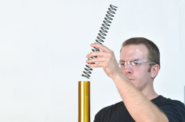
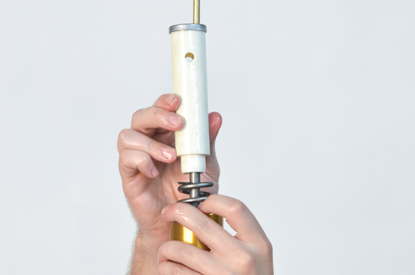
FA14- Install the Fork Spring. If this is a new fork spring you will need to setup preload. The Fork Spring Spacer will probably need to be cut. THIS IS CRITICAL!
|
|
|
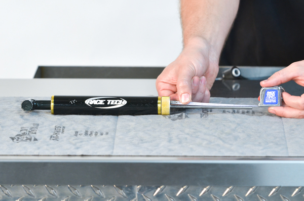
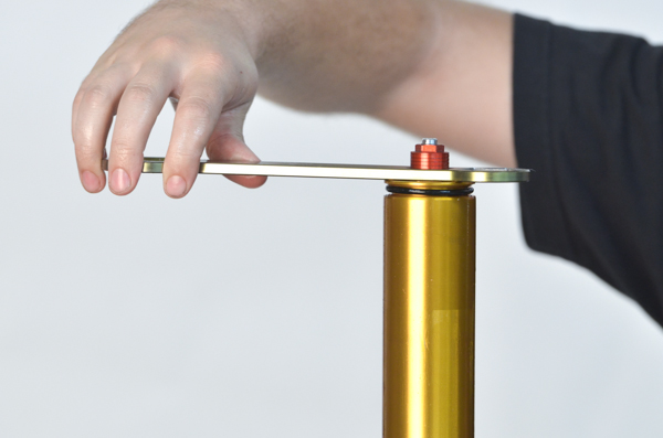
FA15- With the fork tube fully collapsed, measure the distance from the top of the tube to the top of the spring. This reference number will help you calculate the actual preload.
|
|
|
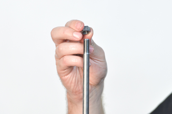
FA16- Install the Rebound Adjusting Rod.
|
|
|
FA17- Attach the Bleeding Tool.
|
|
|
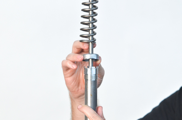
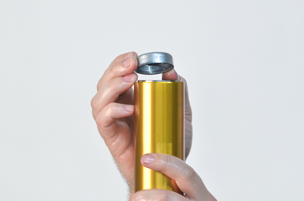
FA18- Install the Preload Tube and special steel cupped washer (cupped side down against the preload spacer).
|
|
|
INSTALL THE FORK CAP
CREATE THE CORRECT NUMBER OF CLICKS
FA19- Make sure the Rebound Adjusting Screw is backed out all the way then screw it in 20 clicks. This step is important in setting the fork cap height and the proper number of clicks of adjustment.
|
|
|
FA20- Tighten the Fork Spring Compressor but make sure you stop before the tool hits the top of the fork tube. Tightening the tool is best accomplished with an electric drill with a socket or a speed handle. Do not use an impact or it will destroy the tool.
|
|
|
FA21- Once the fork is compressed enough extend the damping rod and remove the Bleeding Tool.
|
|
|
FA22- Install the Fork Cap. Make sure the Fork Spring Preload Adjuster is backed out all the way.
|
|
|
FA23- Screw it down until it gently seats the rebound needle.
When the Cap is being screwed on to the Damping Rod the Rebound Adjuster Screw eventually contacts the Rebound Adjuster Rod. As the Cap continues to be screwed on, the Rebound Needle is being compressed until it eventually contacts the Rebound Needle Seat.
If you tighten it with force it will jam the Needle into the Seat and damage this point of contact... so be gentle.
|
|
|
FA24- Bring the jam nut up against the fork cap.
|
|
|
FA25- Back out the adjuster a few clicks to give the Needle clearance from the Seat while you...
|
|
|
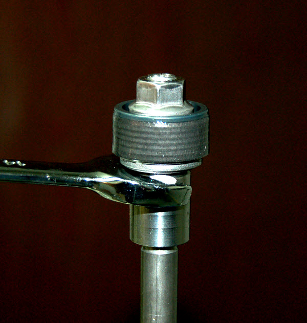
FA26- tighten the Jam Nut.
Check the number of Rebound Adjuster clicks that are available. There should be close to 20 clicks as that is what the procedure we use creates. If it is more than 2 clicks different that take the cap off and repeat the procedure.
|
|
|
FA27- Unscrew the Fork Spring Compressor Tool.
|
|
|
FA28- Once again, measure from the top of the tube to the top of the spring. The difference between this measurement and the one taken before installation is the preload.
Setting Spring Preload is a critical part of the installation process. Many bikes, including this one, has a soft Top-out Spring. This means that the Top-out Spring compresses measurably when the main Fork Spring is preloaded. This makes the fork "grow" during spring installation. It also makes it tricky to setup "Actual Preload".
|
|
|
FA29- Install and tighten the fork cap.
|
|
|
FA30- Gently screw the Rebound Adjuster in clockwise until it stops. Back it out and set it to the proper setting according to the DVS.
|
|
|
FA31- Gently screw the Compression Adjuster in clockwise until it stops. Back it out and set it to the proper setting according to the DVS.
|
|
|
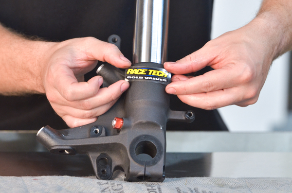
FA32- Most importantly, make sure the surface is clean and install the intensely stylish Race Tech stickers.
|
|
|
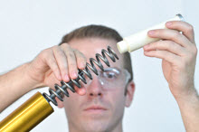
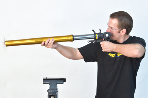
FA33- Strike the classic "I'm pretending it's a gun pose" (but don't let anyone see you.)
|


