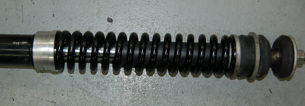
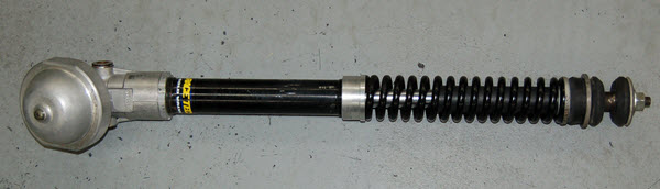
YAMAHA 1975 250/360MX/YZ & 1976 YZ125-360Shock Gold Valve Installation and Rebuild1975 and 1976 models are slightly different. This is an expert level installation that requires machining! The original design has interesting features; the shock and wheel travel are limited by the spring travel. Once the spring coil binds there is a tiny amount of additional bumper flex. One part of the RT mod adds a bottom-out bumper that is simply a 7/8" rubber hose and a new dust seal plate for it to hit squarely on. In stock form the majority of compression damping is created by the base valve which is captive between the shock body and the body eyelet. This valve is very restrictive especially because the shaft is 22mm. The Gold Valve installation transfers the majority of control onto the Gold Valve on the rod. The original N2 pressure ranges from 250 to 360 psi. This causes harshness and sorely limits the performance. We run 100psi. Note: Click on the images to enlarge. Shortcuts: > DISASSEMBLY |
|
|
|
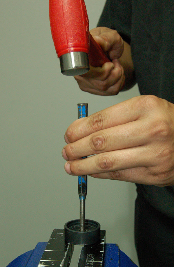
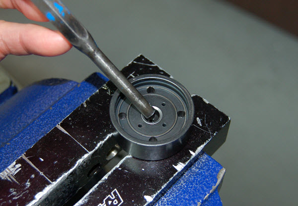
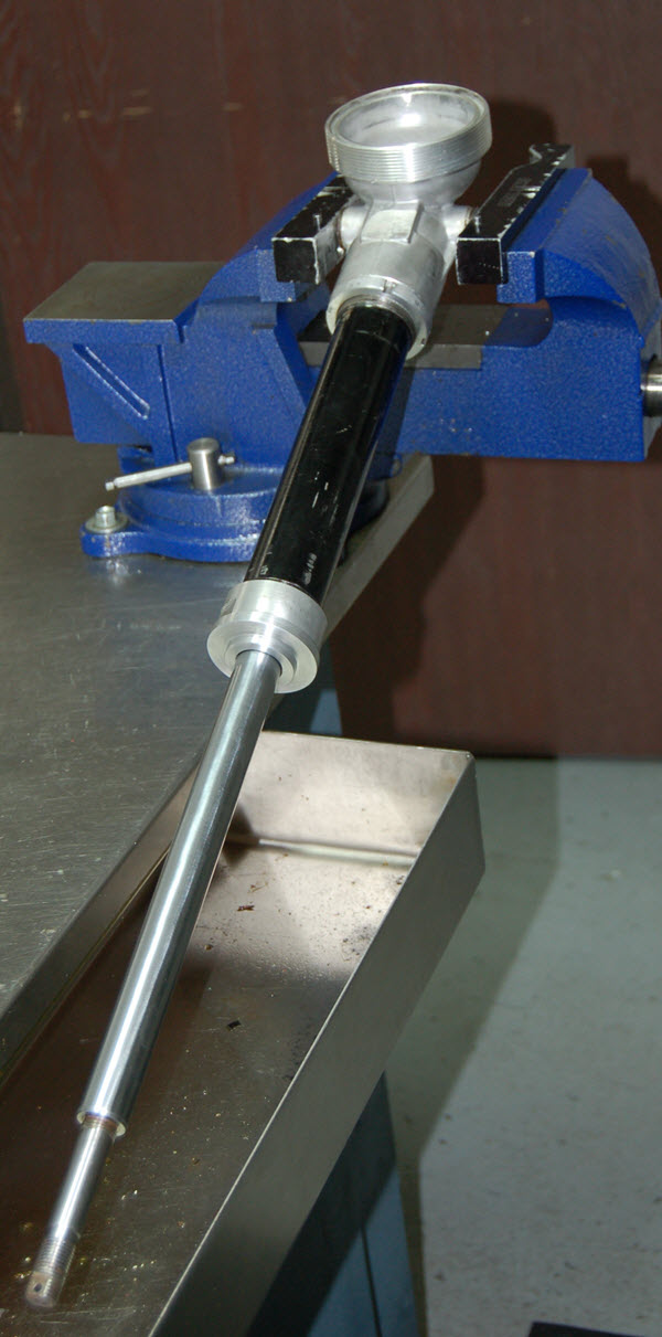
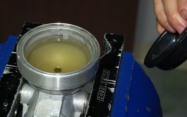
D2- Use a N2 Needle and discharge the shock. Clamp the reservoir diaphram cap in a vise with soft jaws. Unscrew the cap and pump out the oil.
|
|
|
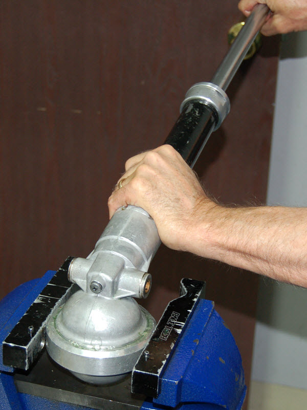
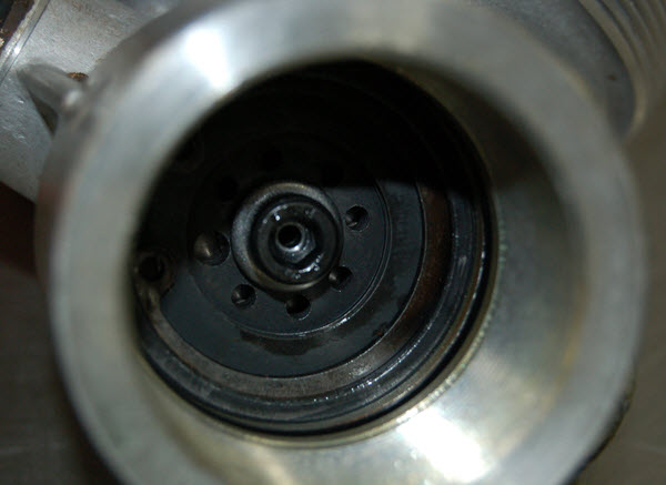
D3- Unscrew the body cap and remove the shaft assembly.
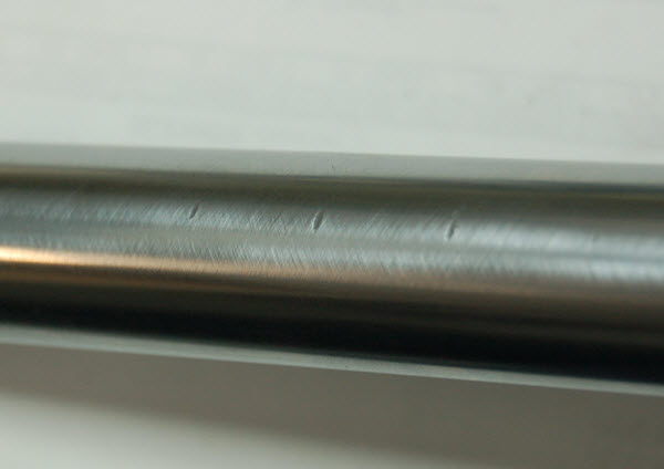
Inspect the shock shaft. It is common for the spring to vibrate so severely that it dents the shaft. On the shocks we have seen these dents are just above the travel and are not a problem.
Any rust in the first 90mm travel (from the seal) requires a shaft rechrome.
|
|
|
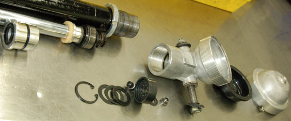
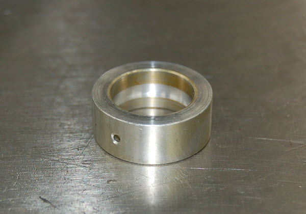
D4- The shock body must be removed from the body eyelet. Loosen the locking collar with Preload Adjuster Tool (TSPA 01). Heat the body at the thread to 280 degrees F with a propane torch. Put the seal head back in the body for support. Clamp the body as close to this support on the end of the body as possible with a 42mm (1975) or 41mm (1976) shaft holding tool in a press. (We shim a 43mm shaft holding tool down to 42.)
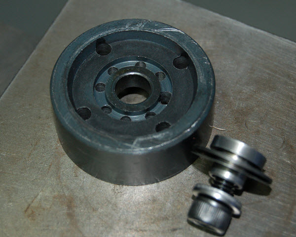
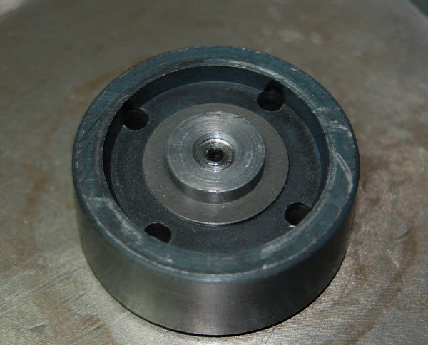
Remove the body cap o-ring. This will allow the base valve to fall out.
Note: This pic shows the Base Valve already unpeened and modified, ready for reassembly.
|
|
|
|
|
|
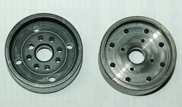
BV2- 1975
For both years the base valve feed holes are too small and there is too much preload on the compression valving.
On the 1975 models there is a 2.5mm pocket and a 2.0mm thick spacer so the stock valving creates 0.5mm preload. Standard valving uses (8) .20x26x9 shims.
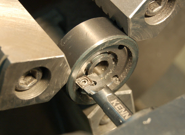
MODIFY THE PISTON - ELIMINATE SHIM PRELOAD
The easiest way to decrease the preload is to machine off the 2.5mm step and make it flat.
Use a boring bar and take a cut starting from the center all the way to the lip (right where the boring bar is in the following picture.)
DRILL THE FEED HOLES
The base valve feed holes (the ones closest to the center) must be drilled to 4.0mm (5/32" or #22).
[In the old days we used to not machine it flat. Instead we would shim the valving stack with (2) .25x21x10 ID shims for 0 preload but machining the piston surface flat is better.]
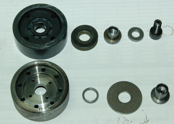
The top pic is a modified 1976 on the left and a stock 1975 on the right.
The bottom pic is a modified 1976 on the top and a stock 1975 on the bottom.
|
|
|
BV3- 1976
MODIFY THE PISTON - ELIMINATE SHIM PRELOAD
On 1976 models there is a 0.20mm step in the piston creating 0.20mm preload. The easiest way to decrease the preload is to machine the surface flat.
Take a skin cut starting from the center all the way to the lip (right where the boring bar is in the picture.)
DRILL THE FEED HOLES
There is not enough room to drill the existing feed holes to 4.0mm as on the 1975. The solution is to drill the (4) existing holes to 2.8mm (7/64" or #35) and add (4) more 2.8mm holes between them for a total of (8) holes.
|
|
|
ALL YEARS
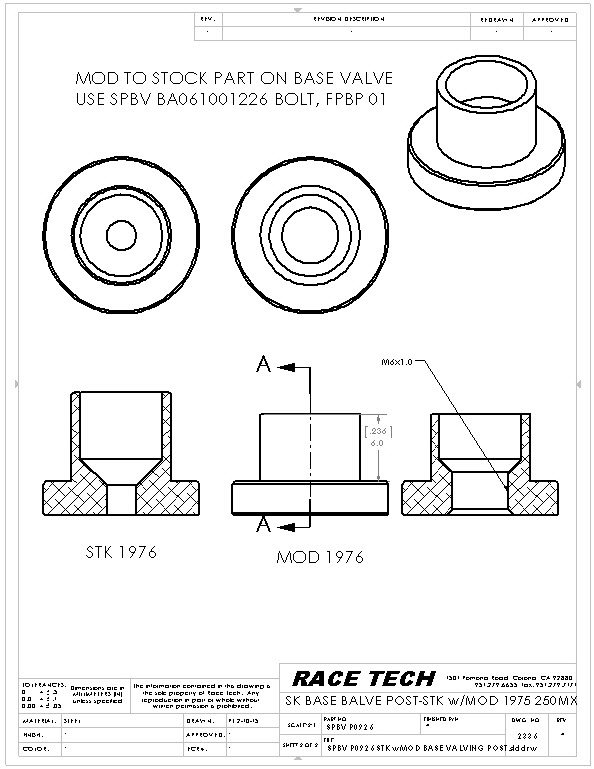
BV4- Shorten the stock center base plate/sleeve and drill and tap it to M6x1.0. This eliminates bleed hole so the thru bolt must add the bleed back in the bolt itself.
See .pdf for specific instructions as the 1975 version is longer. Both are included in the .pdf.
|
|
|
BV4- Shorten the stock base valve post and drill (#8 or 5.0) and tap it to M6x1.0. This eliminates bleed hole so the thru bolt must add the bleed back in the bolt itself.
See .pdf for specific instructions as the 1975 version is longer.
NOTE: The length can be modified on a grinder or belt sander. The exact length is not critical.
|
|
|
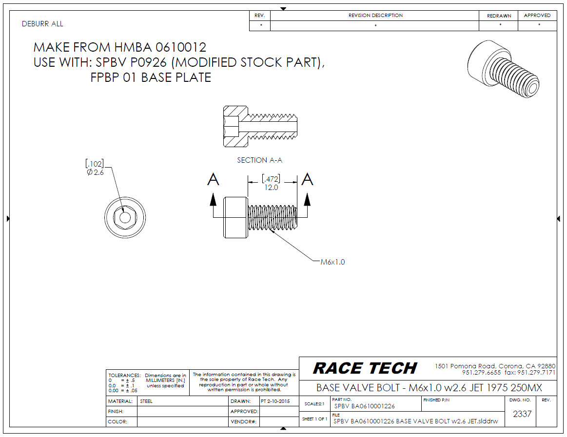
BV5- Make a Valving Bolt by drilling a 2.6mm (#38) bleed hole in a 12mm long M6x1.0 Allen.
|
|
|
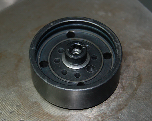
BV6- Build the base valve valving stack. The surfaced pistons eliminate the valving preload.
Assemble the check valve side of the piston (not shown). It has a shim, wave washer, another shim, and is held in with a circlip.
Use a FPBP 01 base plate and Loctite on the bolt.
Pics are of a completed 1976.
|
|
|
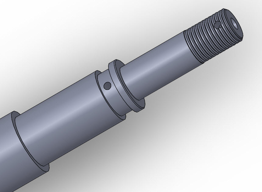
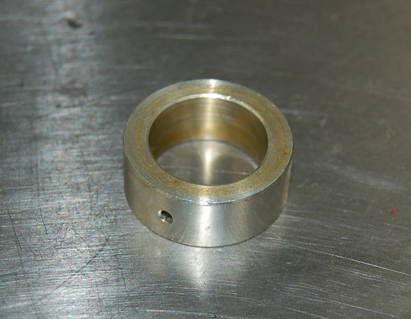
RV2- The Lo-speed rebound bleed flows through the center of the shaft and is controlled by the orifice on the sleeve that fits over this part of the shaft.
1975
The 1975 model (top) is ok as there is a groove in the shaft so the holes don't have to line up exactly however the sleeve must have the hole at the correct end (lined up with the groove).
The 1976 (bottom) does not have a groove in either the OD of the shaft or the ID of the sleeve.
|
|
|
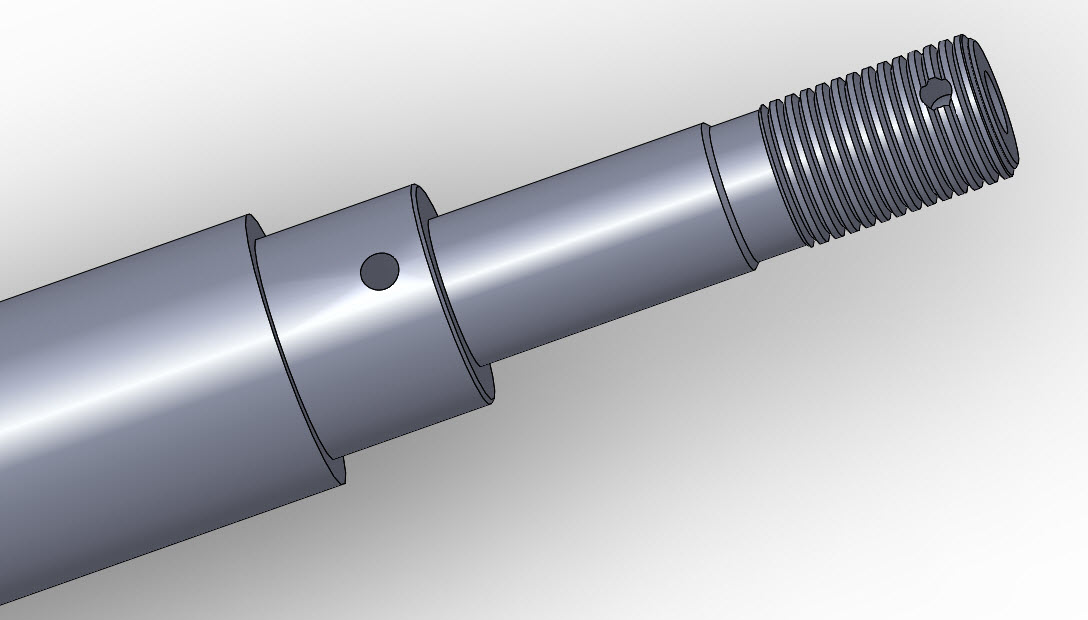
RV3-
1976
The easiest solution for the 1976 is to cut a 2.5 to 3mm wide relief groove in the sleeve so the holes don't have to align. The exact size of the groove is not critical.
|
|
|
RV4- The 1975 has plenty of room for valving on the shaft however the 1976 does not. On the 76 you may need to change the base plate to SPBP 1233 (030) to get a little more room, then valve as usual. This is a pic of a 1976.
Use Loctite and torque the nut to 25 ft-lbs.
|
|
|
|
|
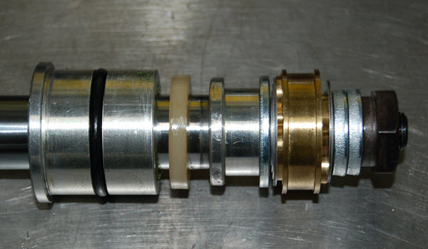
A2- Install the shaft assembly and tighten the seal head.
|
|
|
|
A3- Clamp the body eyelet in a vise with the shaft angling downward at about a 20 degree angle and the reservoir is flat. Fill the shock through the reservoir with US-1 Fluid and stroke the shaft to fill the shock.
|
|
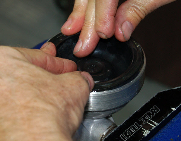
A4- Put your hand over the bottom half of the diaphram opening. Hold the shock upright and stroke it again to remove the trapped air.
|
|
|
|
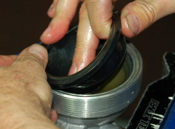
A5- Fill the open reservoir about 2/3 of the way then insert the diaphram. The diaphram has waves in it. Push down on the wave as you insert it into the oil. The oil should overflow and the diaphram should be in its relaxed state.
|
|
|
A6- Apply a little grease on the sealing surface and screw on the reservoir cap. Clamp it on the flats in a vise and tighten.
ALTERNATE FILLING METHOD - The shock can also be assembled dry and bled with a Vacuum Master through the bleed port on the body eyelet.
|
|
A7- Pleasureize, did I say pleasureize? I mean pressurize the shock with a N2 needle to 100 psi.
The stock pressure range is 250-375 psi. The high pressure and large diameter shaft makes the shock extremely harsh.
|
|
|
|
MAKE A BOTTOM-OUT BUMPER
A8- The original design of the shock limits travel with coil bind of the spring (great idea-not really). Once the spring coil binds the rubber bottom-out compresses slightly, even more.
We add a 7/8" rubber hose on the shaft and have it contact 15mm before coil bind. This requires a flat surface for the Hose (bumper) to contact at the seal head.
The stock spring seat has a taper where the hose would hit so we make a new spring seat.
|
|
|
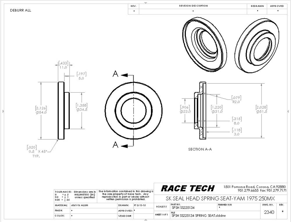
MAKE A NEW SHOCK SEAL HEAD SPRING SEAT
A9- At this point this Spring Seat is machined in-house. SPSH SS225134
Install the new spring seat/bottom-out plate with the felt dust seal underneath. The new plate gives a flat surface for the bottom-out bumper to hit.
|
1976 example:215 EXPOSED SHAFT |
A10- Calculate the bottom-out/hose length required for 15mm bottom-out travel.
Exposed Shaft
(minus) Total Spring Travel
(plus) Preload
(plus) Bottom-out Bumper Travel (15)
= Bumper Hose Length
Rough cut the hose, then slide it over a 7/8" rod to straighten it up and use a belt sander to square up and smooth the ends.
Note: The hose is a 7/8" dishwasher discharge hose. It is buna and has light reinforcement. McFadden- Dale.
Note: 1976 measurements on black spring with RED ID mark. 234 free, 143 coil bind, 91 travel
|
|
A11- Install new Rubber Bumpers.
So far our bumpers are made out of #11 Buna Rubber Stoppers drilled out and chamfered. We are working on a better solution. I'm sure something like this is sitting on a shelf somewhere.
|
|
|
|
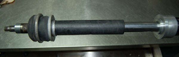
A12- Install the spring, shock mounting hardware and bumpers.
Note: The 1975 has an aluminum spring spacer that can be cut down to decrease preload. Stock it has 14mm (which is, of course, too much).
It would be great to have a selection of springs but I haven't sourced any as of yet.
|
|
|
A13- Place the Race Tech Sticker in an appropriate location for added trickness. Don't bother setting the clickers as there are none, but do enjoy the new ride.
|