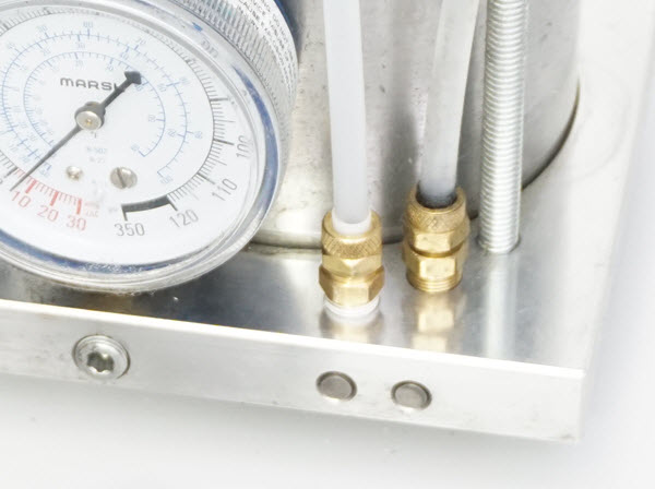
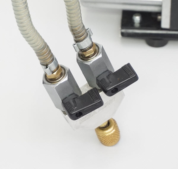
VACUUM MASTER SHOCK FILLING TOOL
|
|
|
|
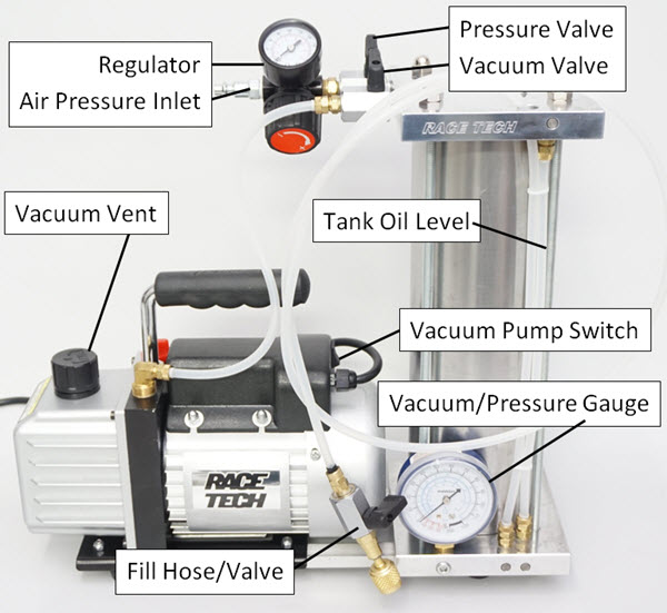
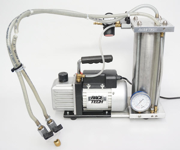
Connect to 110v AC power. Connect dry compressed air or nitrogen and set the regulator to 50 psi.
Fill the Tank with Shock Fluid.
Attach the Fill Tube to the Fill Hose Valve (not too tightly or it can squeeze the rubber gasket excessively and choke it off).
Immerse the Fill Tube into the oil, Open the Fill Hose Valve. Turn on the Vacuum Pump. Open the Vacuum Valve on the top of the tank.
Watch the Tank Oil Level Tube and fill the Tank as much as you want up to within 75mm (3”) from the top. Do not overfill the tank or oil will be drawn out through the Vacuum Pump itself during the shock filling process.
You are ready to vacuum fill shocks.
Pressure Valve Shut
Vacuum Valve Open |
2. BLADDER RESERVOIR - NO BLEED PORT |
|
|
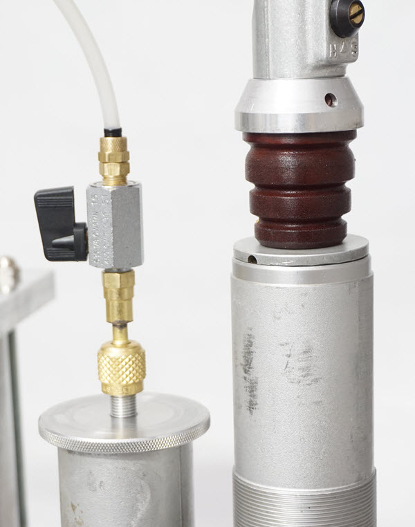
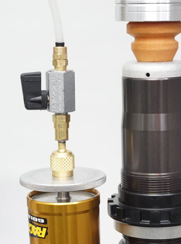
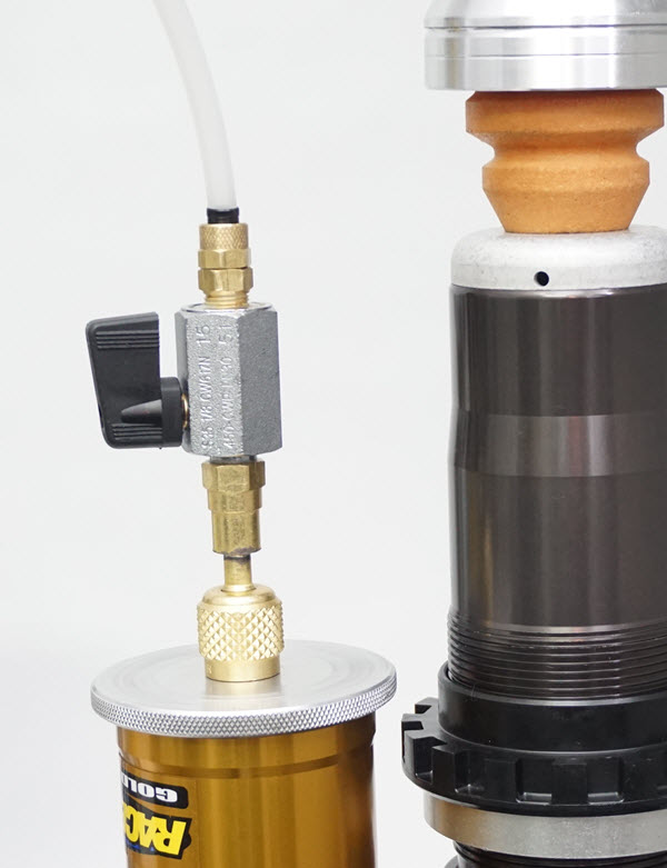
Install the Bladder Adapter and original circlip Install the Plate Attach the Fill Hose to the Bladder Adapter |
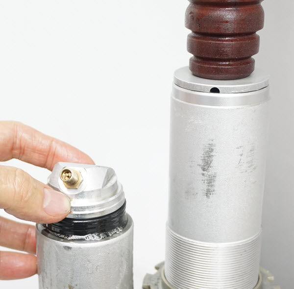
BNB1 - Rebuild the shock dry (without oil and Bladder). Tip: You can start with a normal rebuild with oil already in the shock to save time refilling the tank over the long haul. Mount the shock in a vise (no spring) with the top of the reservoir facing up. Select the appropriate Bladder Adapter. Insert the Adapter into the Reservoir and install the stock clip.
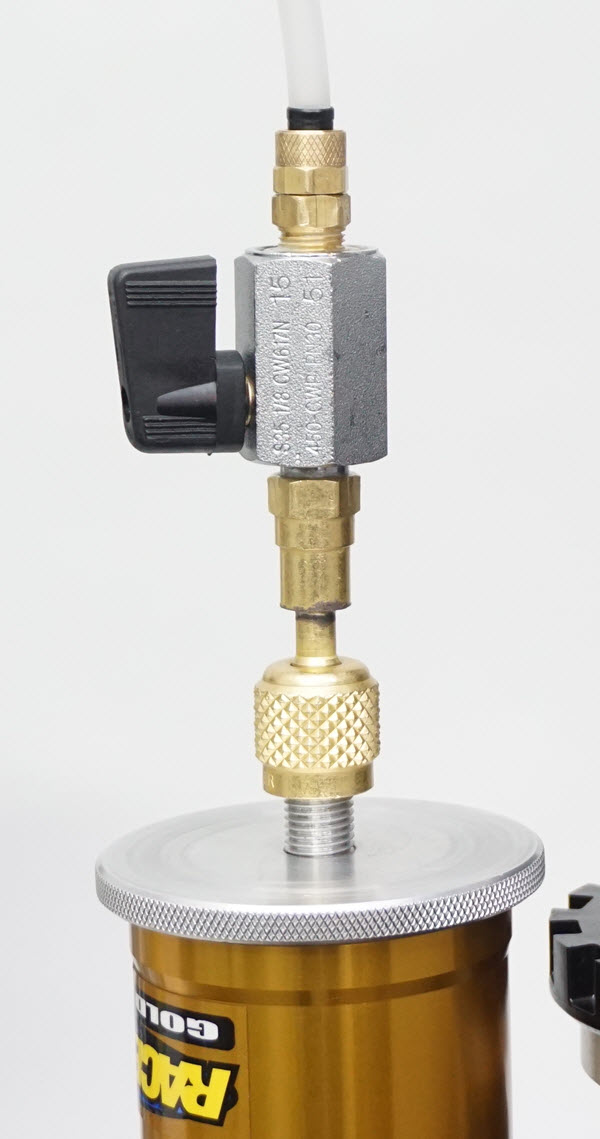
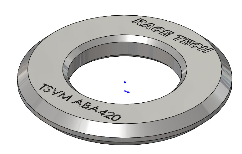
Thread on the Bladder Adapter Plate (TSVM ABP70) and tighten it. Attach the Fill Hose and open the Fill Valve.
The Fill Valve will remain open throughout the filling process.
Bladder Adapter
Bladder Adapter Plate
With Stepped Reserviors you will need an Adapter plate on top of the Bladder Adapter, under the circlip
|
|
BNB2 - Draw a vacuum in the shock.
Turn on the Vacuum Pump. Open the Vacuum Valve on the top of the tank.
The shock will compress as the air is vacuumed out. Let it continue to draw down for about 15 seconds. Turn off the pump and close the Vacuum Valve on the tank.
Shock Collapsed Under Vacuum
|
|
| BNB3 - Fill the shock with oil.
Open the Pressure Valve (50 psi) to fill the shock with oil. Do not worry about the “air” in the fill hose as these bubbles are actually vacuum pockets, not “air”. The shock will extend as it fills. Twist the shaft if you need to help it along. After the shock is fully extended, stroke the shock a few times. |
|
|
BNB4 - Depressurize the Oil Tank.
Close the Pressure Valve. Then slowly open the Vacuum Valve. This will release pressure through the pump.
If you open it too quickly or you are using too much positive pressure it will blow oil back out of the pump vent.
Repeat - If you would like you can repeat the procedure but it is usually not nesessary.
|
|
|
BNB5 - At this point there is too much oil in the shock. Depressurize the tank by opening the Vacuum Valve. Compress the shock shaft. Back the Adapter Plate off until it hits the Fill Hose Valve.
Then, while holding the shock shaft down, press the Adapter Plate down to the top of the reservoir. Some, but not all, of the extra oil will be pushed out of the shock.
Disconnect the Fill Hose from the Adapter. Remove the clip and the Adapter.
Adapter pushed down to Plate to remove some excess oil
|
|
|
BNB6 - Put the Bladder on the Cap and pressurize it just enough so the bladder is full (2-3 psi)(not collapsed). With the shock shaft compressed insert the bladder assembly into the Reservoir, allowing the oil to overflow.
To avoid waste, you can remove a bit more of oil from the reservoir before inserting the bladder. However, make sure there is enough oil in the reservoir so it overflows when the bladder is inserted.
The reservoir must overflow when immersing the Full Bladder
|
|
|
BNB7 - Insert the Clip, seat the Cap, and pressurize the shock with nitrogen to the recommended setting.
|
|
3. PISTON RESERVOIR - WITH A BLEED PORT |
|
|
PWB1 - Rebuild the shock dry (without oil). You can start with a normal rebuild with oil already in the shock to save time refilling the tank over the long haul.
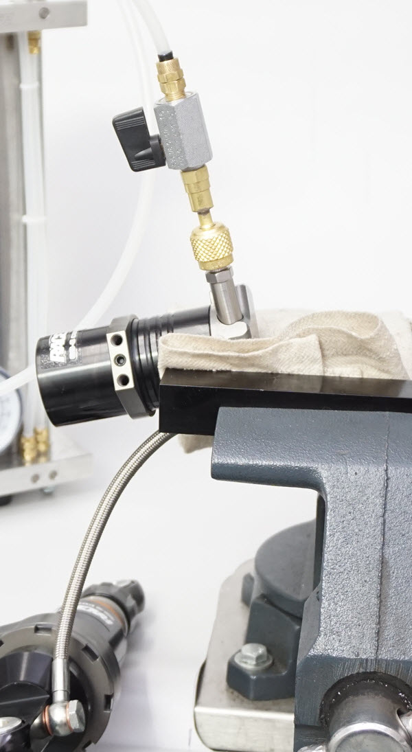
Mount the shock in a vise (no spring) with the bleed port at its highest point.
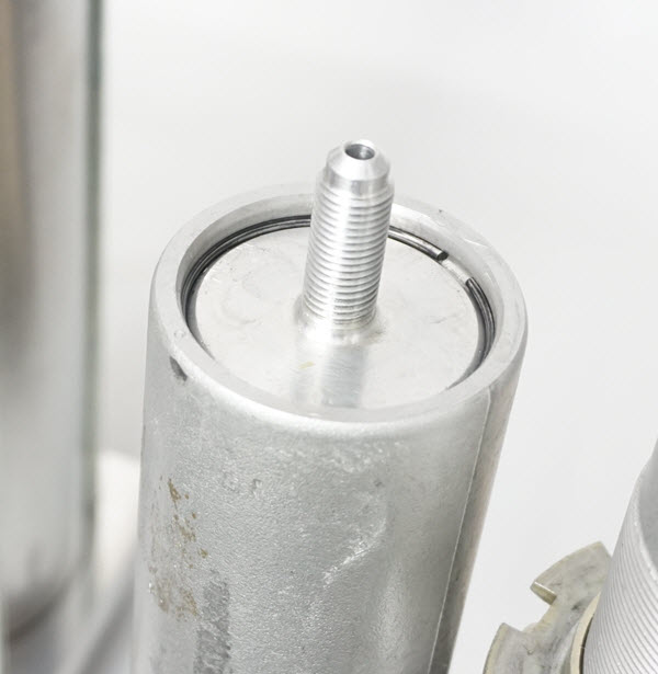
Select the appropriate Adapter. Remove the Bleed Screw and attach the Adapter to the shock. Attach the Fill Hose and open the Fill Valve.
The Fill Valve will remain open throughout the filling process.
Remove the nitrogen filling cap and/or Schrader core. This allows the piston to move more freely.
|
|
| PWB2 - Draw a vacuum in the shock. Open the Fill Hose Valve. Turn on the Vacuum Pump. Open the Vacuum Valve on the top of the tank.
The shock will compress and the reservoir piston will be drawn to the shock end of the reservoir as the air is vacuumed out. Let it continue to draw down for about 15 seconds. Turn off the pump and close the Vacuum Valve on the tank. |
|
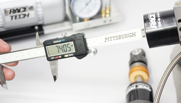
| PWB3 - Measure the distance from the end of the reservoir to the Reservoir Piston at maximum air volume.
In this case it is about 74mm.
|
|
|
PWB4 - Fill the shock.
Open the Pressure Valve (50 psi) to fill the shock with oil. Do not worry about the “air” in the fill hose as these bubbles are actually vacuum pockets, not “air”.
The shock will extend as it fills. Twist the shaft if you need to help it along.
After shock is fully extended stroke the shock a few times.
Shock Extended Under Pressure
|
|
|
PWB5 - Depressurize the Oil Tank.
Close the Pressure Valve. Then slowly open the Vacuum Valve. This will release pressure through the pump.
If you would like you can repeat the procedure but it is usually not nesessary.
|
|
|
PWB6 - Set the Reservoir Piston height.
After the oil tank is depressurized, push the Reservoir Piston to the manufacturer’s suggested height—usually 10 to 15mm from the shock end (not the nitrogen end). This will push the extra oil back into the tank. Make sure the shock shaft is fully extended.
Measure the distance with a caliper or a rod that fits in the hole. In this case it is set to about 64mm. This is 10mm from the fully bottomed out distance of 74mm.
|
|
 |
PWB7 - Close the Fill Hose Valve. Disconnect the Fill Hose from the Adapter. Remove the Adapter. Replace the Bleed Port Screw and pressurize the shock to the recommended setting. Make sure any required o-rings are in place.
|
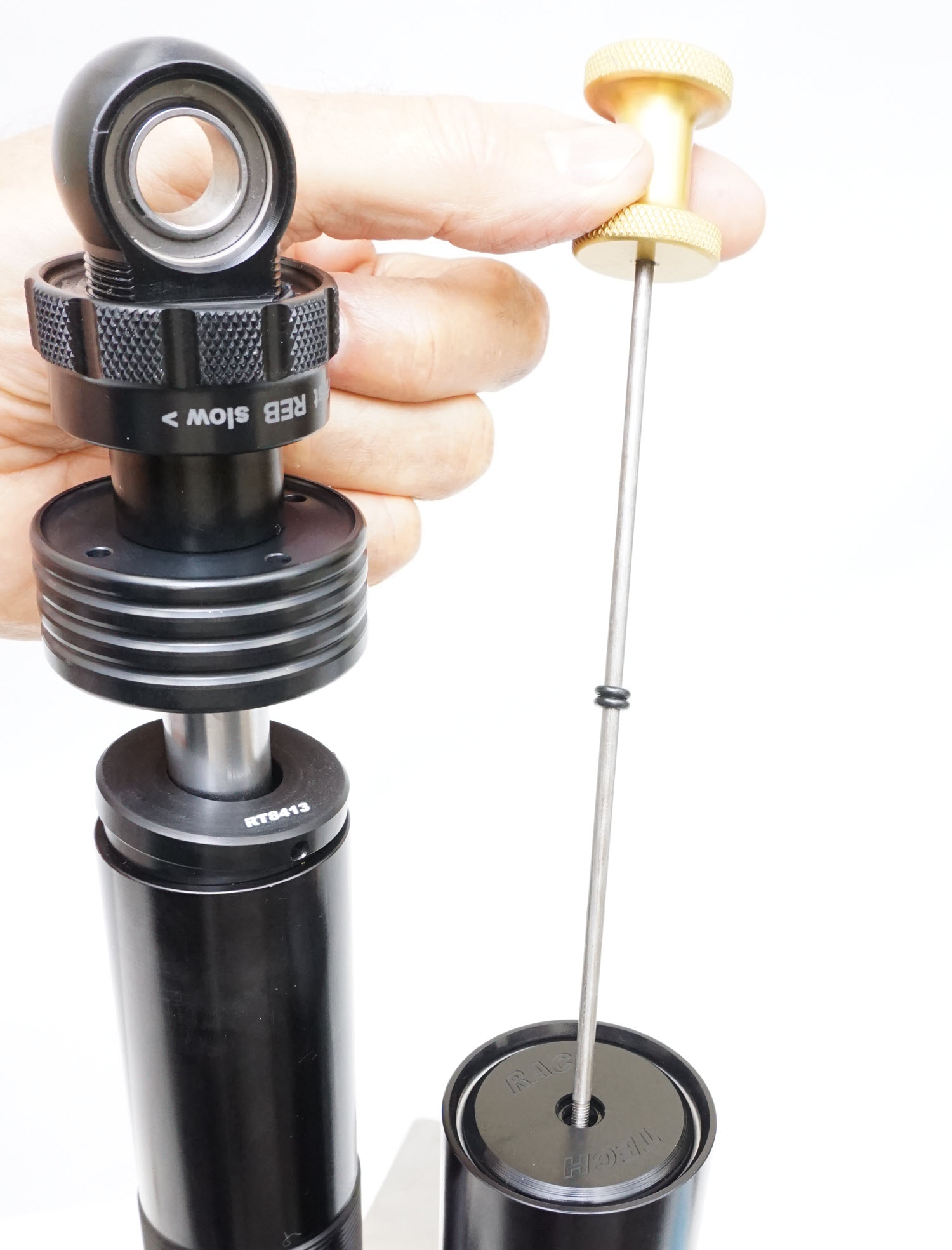
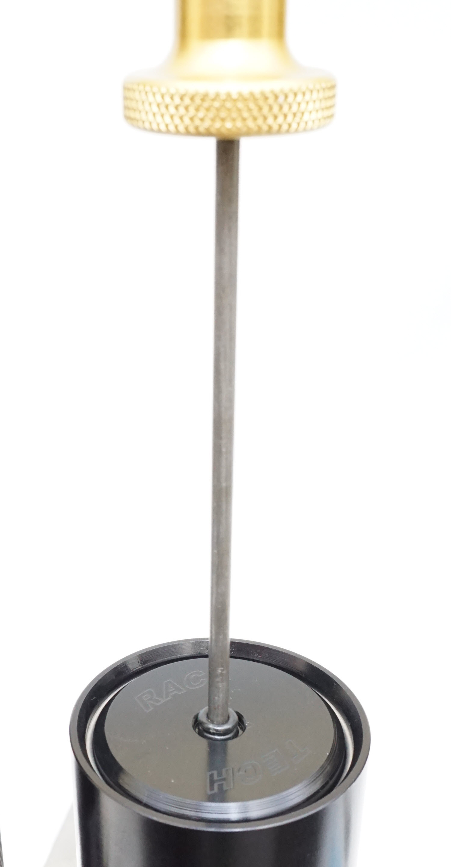
| PWB8 - Alternate method of setting the piston height using the TSRS 03050 Reservoir Piston Setting Tool.
1. Insert the tool through the charging port. On a G3-S Shock the tool can be threaded into the Reservoir Piston. This "threading in" step is not required but it allows you to pull up on the Piston (as in a hand bleed) instead of just pushing. 2. As in PWB3 instead of measuring the distance to the piston, push both o-rings until they touch the Reservoir Cap. 3. Once the shock is filled with oil the Piston will move up until it hits the Cap. At this time move the lower o-ring 10mm. 4. After the oil tank is depressurized, push the piston down until the lower o-ring just touches the Cap. Remove the tool. Install the Schrader Valve Core (if used). Fill with Nitrogen to the proper pressure. |
|
4. MAINTENANCE |
|
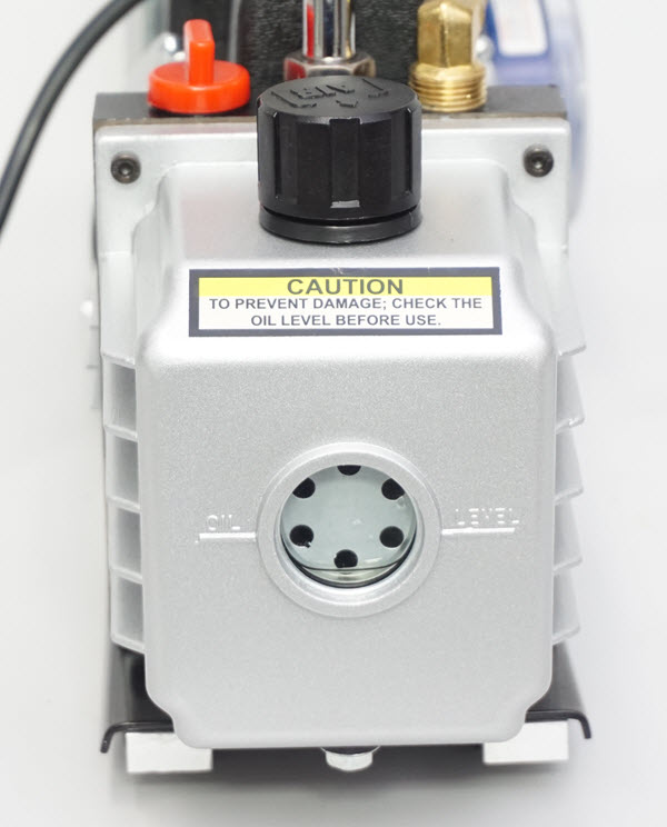 |
Periodically check oil level through the View Port on the side of the pump. During use, some of the suspension fluid will be pulled into the pump (particularly if the Tank is overfull). When the pump becomes overfull open the Vacuum Valve, turn on the pump, and draw a vacuum on the tank.
Shut off the Pump Switch with the Vacuum Valve still open. Oil will be drawn from the pump back into the Tank. Shut the Vacuum Valve when the level in the View Port is drawn down to the mid level.
The Vacuum Pump is filled with suspension oil. Use the same oil in the Vacuum Pump as in the shocks.
|
5. REPLACEMENT PARTS |
|
|
|
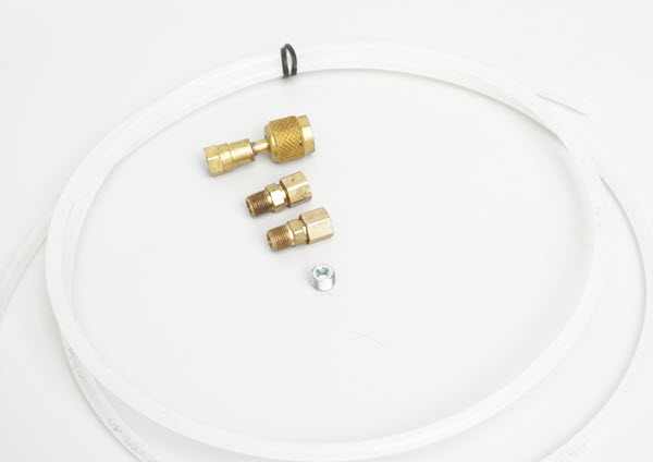
TSVM SC01 - Single Hose Conversion Kit
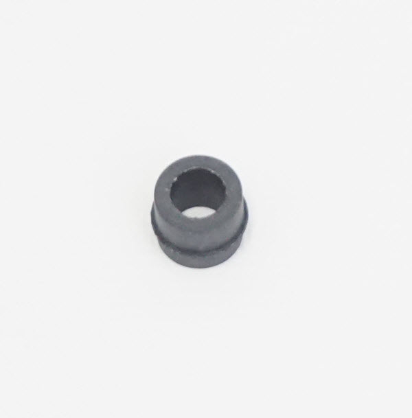
TPVM CHSP511 – Quick Connector Seal
TSVM RG01 - Regulator Assy |
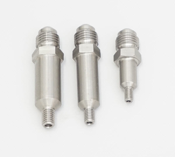 |
6. FLAT HEAD BLEED PORT ADAPTERS TSVM AM04070 – 90° M4x.7 TSVM AM05080 – 90° M5x.8 TSVM AM06100 – 90° M6x1.0 |
 |
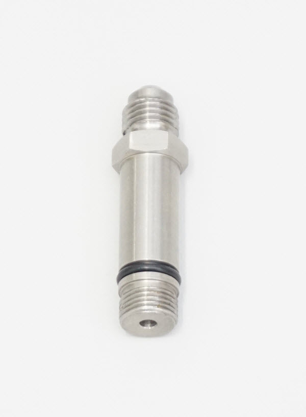
WP SHOCK ADAPTER
TSVM AS3828WP 3/8”-28
|
 |
ÖHLINS STEERING DAMPER ADAPTER
TSVM AM11100 – M11x1.0
|
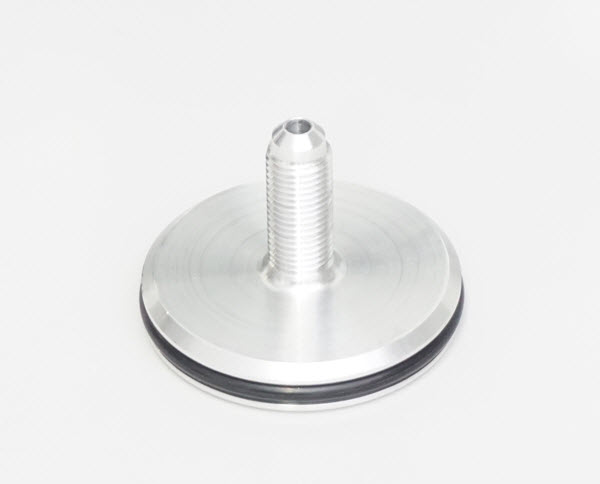 |
BLADDER ADAPTERS
TSVM AB40
TSVM AB46
TSVM AB48.5
TSVM AB52
TSVM AB54
TSVM AB57
TSVM AB60
TSVM AB64
|
 |
BLADDER ADAPTER PLATE
TSVM ABP70
(used with all Bladder Adapters)
|
 |
FILL TUBE
TSVM FT01
|
7. SINGLE HOSE CONVERSION (TSVM SC01) |
|
| SC1 - This converts the original Dual Hose to a Single Hose System
Empty the suspension oil from the tank. |
|
| SC2 - Remove the Vacuum Hose from the top of the tank to the Control Head and plug the hole with the 1/8" NPT Plug. Use Teflon pipe tape.
|
|
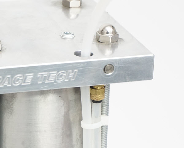
| SC3 - Remove the Fill Hose and fitting from the Bottom Plate and install the new Hose Fitting with pipe tape. | |
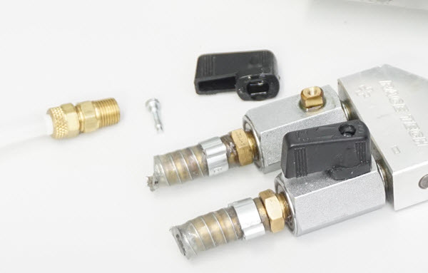
| SC4 - Disassemble the Control Head by removing the lever from one of the ball valves. Unscrew the ball valve and remove the hose barb. | |
| SC5 - Assemble the new single Fill Hose starting with the Quick Connector, Ball Valve, and the new Hose Compression Fitting. Use Teflon pipe tape.
Attach the hose to the Filler Head. Feed the other end of the new hose through the hole in the top plate. Attach it to the new fitting on the bottom plate. Refill the tank and you are ready to go. (Life is easy now - tell mom!) |
|
|
|
|
|
|
|

